Vehicle network, device and method for the coordination thereof

a vehicle network and vehicle technology, applied in vehicle position/course/altitude control, process and machine control, instruments, etc., can solve the problems of inability to precisely predict difficult to adjust the drive power required for a desired change in ground speed, and difficulty in predicting the movement of the vehicle relative to one another, so as to prevent fluctuations in the quality of the transferred crop, the parameters of the processing of the crop in the first vehicle can be held, and the effect of shor

Active Publication Date: 2016-05-10
CLAAS SELBSTFAHRENDE ERNTEMASCHINEN GMBH
View PDF6 Cites 6 Cited by
  • Summary
  • Abstract
  • Description
  • Claims
  • Application Information

AI Technical Summary

Benefits of technology

[0009]To that end, the present invention provides a device and a method for rapidly and accurately controlling a displacement of the impact point.
[0011]The control unit is preferably designed to control the ground-speed differential by changing the ground speed of the second vehicle. While this is underway, if the first vehicle moves at a constant ground speed through the crop stand, the crop throughput in the first vehicle does not change. The parameters of the processing of the crop in the first vehicle can therefore be held constant, and fluctuations in the quality of the transferred crop can be prevented.
[0012]The device preferably comprises at least one actuator for moving the transfer device relative to a reference point on the first vehicle. Since substantially less mass needs to be accelerated or slowed down in order to adjust the transfer device than is the case in order to change the ground speed of a vehicle, this adjustment is implemented in a short period of time, even across a greater distance. The impact point is rapidly shifted from one point at which there is risk of overfilling to the vicinity of a point where filling is still possible. This inventive operation eliminates the risk, at the moment, of locally overfilling the loading chamber despite a potential inaccuracy in the adjustment of the transfer device. More time is therefore available for correcting the inaccuracy and, since this correction is implemented by the vehicle ground speed, the transfer device is prevented from oscillating, which would occur if the movement thereof could not be sufficiently controlled.
[0013]The control unit should is set up to calculate, between a redetermination of the target position and the detection of the position of the impact point, an adjustment of the actuator required to displace the impact point to the target position and to control the calculated adjustment. By adjustment of the transfer device, it is possible to implement a majority of the desired displacement of the impact point in a brief period of time and so, if the position of the impact point is detected, the deviation from the target position needed to be eliminated by controlling the ground-speed differential is still minimal and is eliminated in a short period of time.
[0017]Advantageously, the camera is mounted on the transfer device. Given that the camera moves along with the transfer device, the position of the impact point in the images delivered by the camera change very little when the transfer device is displaced, thereby simplifying the automatic detection of the impact point in the images. By contrast, reference points on the loading surface move to an extreme extent in the images delivered by the camera when the transfer device is moved. Unlike the impact point, these reference points are configured in terms of color or shape to automatically identify in the images.
[0027]In order to minimize the time required to bring the detected position in agreement with the target position, it is advantageous to implement a step b) in advance, namely that of calculating an adjustment of an actuator (11, 12) required to shift the impact point to the target position and controlling the adjustment.

Problems solved by technology

Harvesting machines in the form of forage harvesters are typically not designed to store notable quantities of crop on board.
This results in the problem, however, that the vehicles need time to make adjustments in ground speed to adapt to a change in the target ground speed, thereby making it difficult to predict the movement of the vehicles relative to one another and to predict a resultant displacement of the impact point of the crop on the second vehicle during a change in ground speed.
In addition, it is difficult to exactly predict and adjust the change in drive power required for a desired change in ground speed.
Although it is possible, in a closed control loop, to measure a change in ground speed resulting from a change in drive power and to subsequently correct the drive power if necessary, this requires a considerable amount of time.
Therefore, it is difficult to control a rapid and simultaneously accurate displacement of the impact point by means of a change in the vehicle ground speed.

Method used


Image

  • Vehicle network, device and method for the coordination thereof
  • Vehicle network, device and method for the coordination thereof
  • Vehicle network, device and method for the coordination thereof

Examples


Embodiment Construction

[0036]The following is a detailed description of example embodiments of the invention depicted in the accompanying drawings. The example embodiments are presented in such detail as to clearly communicate the invention and are designed to make such embodiments obvious to a person of ordinary skill in the art. However, the amount of detail offered is not intended to limit the anticipated variations of embodiments; on the contrary, the intention is to cover all modifications, equivalents, and alternatives falling within the spirit and scope of the present invention, as defined by the appended claims.

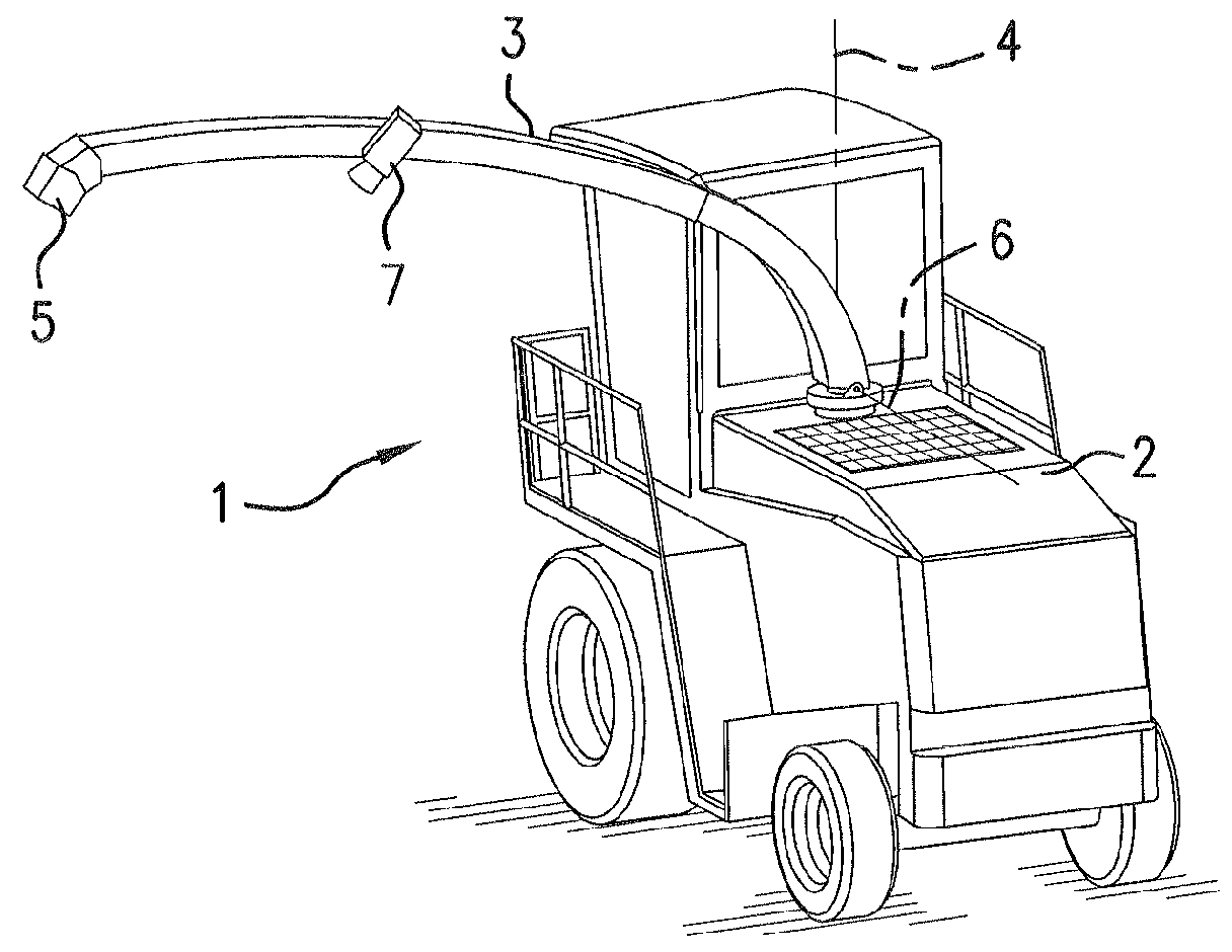
[0037]FIG. 1 shows a forage harvester 1 as an example of a vehicle used as the first vehicle within the scope of a vehicle network according to the invention. A front harvesting attachment is mounted on a front side of the forage harvester 1 (not shown), which faces away from the observer. A machine housing 2 of the forage harvester 1 contains a chopping assembly for chopping crop that is p...


PUM


Abstract

A device for coordinating a first vehicle with a transfer device and a second vehicle with a loading chamber that is filled by the transfer device includes a monitoring device for monitoring the transfer from the first vehicle to the second vehicle and a control unit. The control unit relies on the monitoring device to detect a position of an impact point of a load crop stream discharged from a transfer device of the first vehicle to the second vehicle and, in the event the detected position deviates from a target position, the control device sets the ground-speed differential to be different from zero until the detected position matches the target position.

Description

CROSS-REFERENCE TO A RELATED APPLICATION[0001]The invention described and claimed hereinbelow is also described in German Priority Document DE 20 2013 012026.8, filed on Jul. 19, 2013. The German Priority Document, the subject matter of which is incorporated herein by reference, provides the basis for a claim of priority of invention under 35 U.S.C. 119(a)-(d).BACKGROUND OF THE INVENTION[0002]The invention relates to a vehicle network of two vehicles working in a coordinated manner, such as a harvesting machine and a hauling vehicle that receives crop from the harvesting machine and a device and a method for the coordination thereof.[0003]Harvesting machines in the form of forage harvesters are typically not designed to store notable quantities of crop on board. Instead, the crop to be chopped is continuously transferred to a hauling vehicle traveling adjacent thereto. Although harvesting machines in the form of combine harvesters usually comprise installed crop storage devices and ...

Claims


Application Information

Patent Timeline
Patent Type & Authority Patents(United States)
IPC IPC(8): G06F19/00A01D57/00G05D1/02A01D43/07
CPCA01D57/00A01D43/07G05D1/0287A01D43/073G05D1/0293G05D2201/0201
Inventor KRAUSE, THILOMIDDELBERG, RENE
Owner CLAAS SELBSTFAHRENDE ERNTEMASCHINEN GMBH
Why Eureka
Try Eureka