Engine cooling system using a water pump and a solenoid valve

a technology of solenoid valve and water pump, which is applied in the direction of valve operating means/release devices, machines/engines, mechanical apparatus, etc., can solve the problems of variable water pump disadvantage in terms of manufacturing cost and controllability, mechanical water pump disadvantage in terms of fuel efficiency, and inability to actively control the flow of coolant, etc., to achieve the effect of reducing the amount of space occupied

Active Publication Date: 2020-06-11
HYUNDAI MOTOR CO LTD +1
View PDF0 Cites 1 Cited by
  • Summary
  • Abstract
  • Description
  • Claims
  • Application Information

AI Technical Summary

Benefits of technology

The present invention is about an engine cooling system that can quickly and accurately control the flow of coolant without using a complicated electronically variable water pump. The system can also simultaneously control and distribute the flow of coolant by controlling the solenoid valve, which can open or close the inlets of multiple coolant passages. The coolant passages can be directed to different parts of the engine for separate cooling, and the system can quickly warm up the coolant when the engine is cold. The solenoid valve can be built into the water pump for space-saving purposes.

Problems solved by technology

The mechanical water pump is disadvantageous in terms of fuel efficiency because it cannot be controlled in various manners according to the engine and environmental factors.
On the other hand, the variable water pump is disadvantageous in terms of manufacturing costs and controllability because it uses a control mechanism with a complex structure to control the flow rate.
As described above, since the mechanical pump operates in proportion to the number of revolutions of the engine, it is impossible to actively control the flow of coolant.
However, the conventional variable water pump is problematic in that, due to a complicated structure, it is difficult to secure durability and it is costly to manufacture and subjected to restricted installation space in the engine system and compartment.

Method used


Image

  • Engine cooling system using a water pump and a solenoid valve
  • Engine cooling system using a water pump and a solenoid valve
  • Engine cooling system using a water pump and a solenoid valve

Examples


Embodiment Construction

[0032]Embodiments of the present disclosure are described below in more detail with reference to the accompanying drawings. The present disclosure may, however, be embodied in different forms and should not be construed as limited to the embodiments set forth herein. Rather, these embodiments are provided so that this disclosure will be thorough and complete, and will fully convey the scope of the present disclosure to those having ordinary skill in the art. Throughout the disclosure, like reference numerals refer to like parts throughout the various figures and embodiments of the present disclosure.

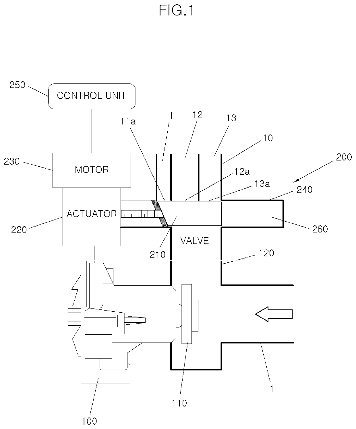
[0033]FIG. 1 is a diagram illustrating an engine cooling system according to an embodiment of the present disclosure.

[0034]As illustrated in FIG. 1, the engine cooling system according to the present disclosure includes a water pump 100, a coolant passage 10 having a plurality of passages 11, 12, and 13, and a solenoid valve 200.

[0035]The water pump 100 functions to discharge coolant fro...


PUM


Abstract

An engine cooling system may include: a water pump for supplying coolant to an engine system; a plurality of coolant passages for connecting the water pump to individual constituent components of the engine system; a solenoid valve disposed between an outlet of the water pump and inlets of the coolant passages to integrally control a flow of coolant from the water pump to the coolant passages; and a control unit for controlling the solenoid valve. The inlets of the respective coolant passages are adjacent to each other side by side in a width direction of the outlet of the water pump. The inlets of the respective coolant passages are sequentially opened and closed by moving a spool of the solenoid valve in the width direction.

Description

CROSS-REFERENCE TO RELATED APPLICATIONS[0001]This application claims priority to Korean Patent Application No. 10-2018-0156338, filed on Dec. 6, 2018, which is incorporated herein by reference in its entirety.BACKGROUNDField of the Disclosure[0002]Embodiments of the present disclosure relate to an engine cooling system; and, particularly, to an engine cooling system using a water pump and a solenoid valve.Description of Related Art[0003]In general, an engine cooling system for vehicles cools an engine by a water-cooling method using coolant. To this end, as disclosed in Korean Patent No. 10-1786701, a water pump is used to discharge the coolant stored in a coolant storage tank by rotating a pump impeller and to supply the coolant to the constituent components, such as a cylinder head, a cylinder block, and a radiator, of an engine in an engine system.[0004]Examples of the water pump include a mechanical water pump that is driven in proportion to the number of revolutions of an engin...

Claims


Application Information

Patent Timeline
Patent Type & Authority Applications(United States)
IPC IPC(8): F01P7/14F04D13/06
CPCF01P7/14F04D13/06F01P7/16F01P3/02F01P5/12F01P2007/146F01P3/20F01P7/165F01P2060/04F01P2060/08F01P2070/10F01P5/10F01P2060/18F16K31/0644F02M26/28
Inventor LEE, HYO-JO
Owner HYUNDAI MOTOR CO LTD
Why Eureka
Try Eureka