
Corrosion resistant, environmentally sealing, electrically conducting, cable connector

a technology of corrosion resistance and environmental sealing, applied in the direction of conductive connectors, insulated conductors, cables, etc., can solve the problems of low conductivity, easy corrosion, and low conductivity, and achieve excellent corrosion resistance, low conductivity, and corrosion resistance.

Inactive Publication Date: 2016-04-19
USA REPRESENTED BY THE SEC OF THE NAVY
View PDF9 Cites 3 Cited by
  • Summary
  • Abstract
  • Description
  • Claims
  • Application Information

AI Technical Summary

Benefits of technology

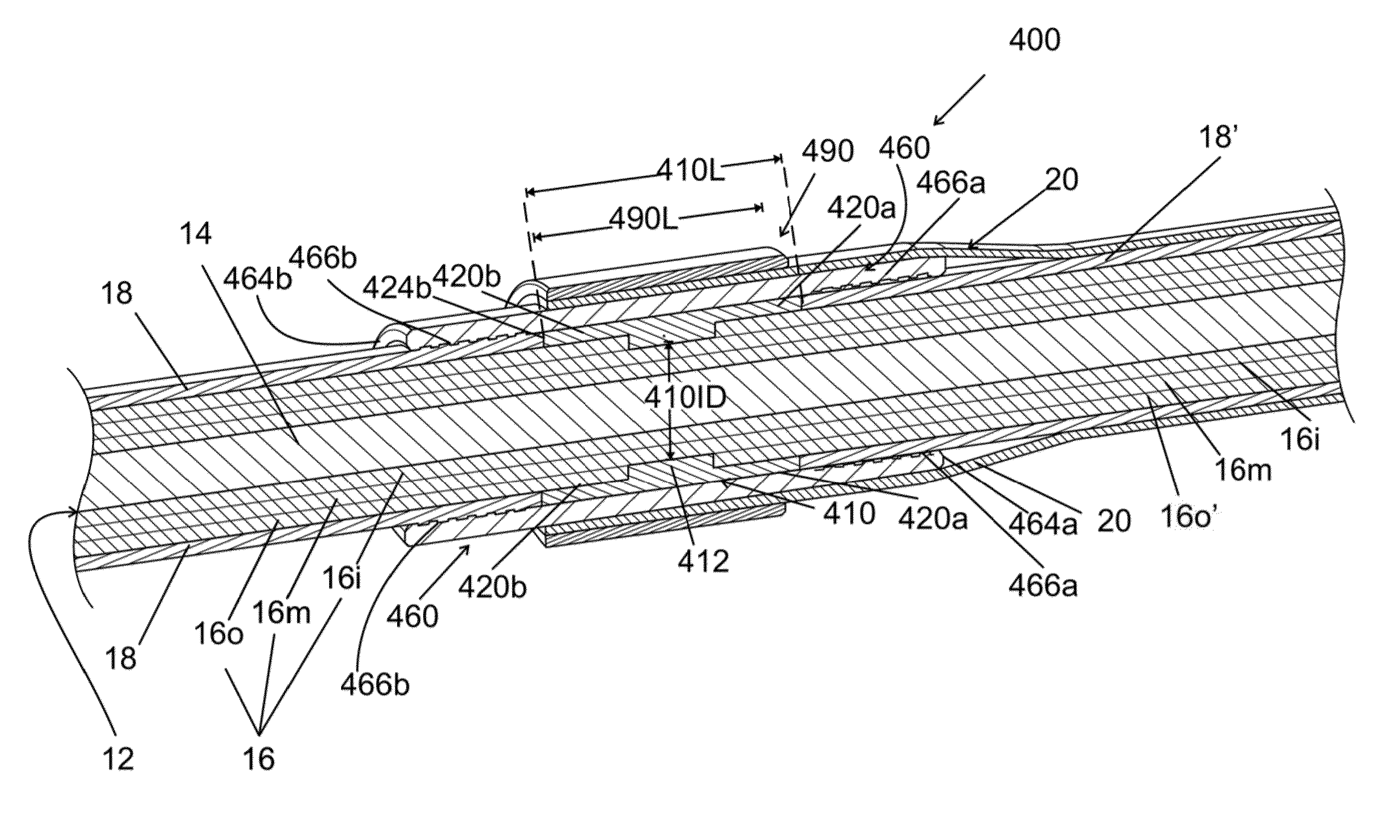
[0004]The invention provides a compact, corrosion resistant, environmentally sealing, conductive connector for creating a water tight electrical connection between an inner conductor of a coaxial cable and an outer conductor, where the outer conductor is overlaying a peripheral section of the coaxial cable. The inner conductor and the outer conductor can be two dissimilar metals, each used for its unique properties while their negative properties are avoided. For example, aluminum is an excellent conductor and lightweight, but corrodes easily so it is kept sealed in the cable by the sealing action of the connector. Titanium has excellent resistance to corrosion, but it has low conductivity so it can only be used efficiently by keeping conductive lengths to a minimum.
[0010]In another subsequent step, an electrical joint compound can be applied to the exposed layers of the inner conductor and the conductors after they are manually abraded with a wire brush. The electrical joint compound in combination with abrasion generally is selected to reduce electrical resistance as the abrasion and joint compound break up and dissolves any oxides formed on the inner conductor. It also provides protection for the connection against the harmful effects of the environment.
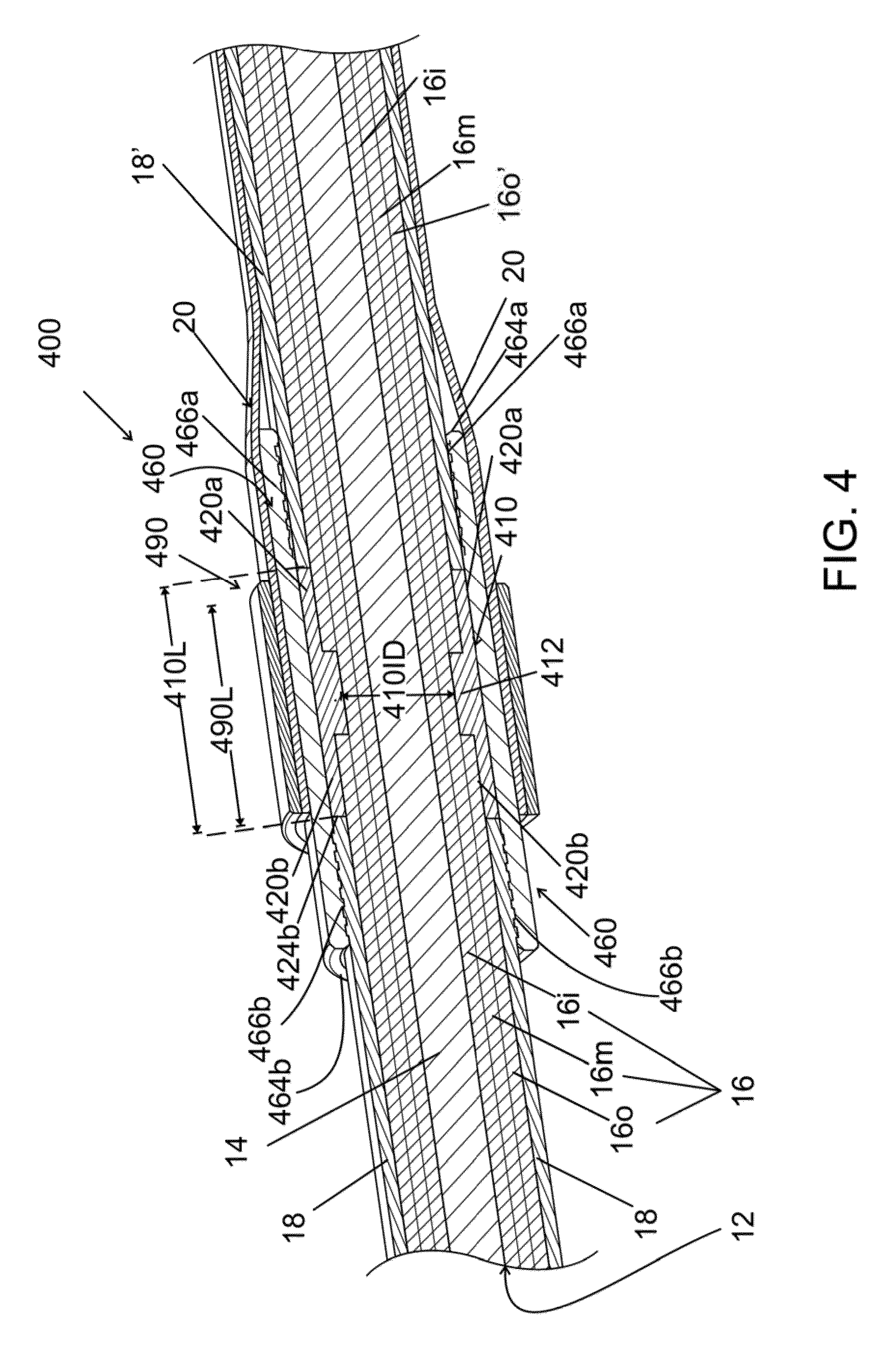
[0011]The pair of intermediate halves is assembled in the notch, such that the center wall contacts the middle layer, the flanking walls contact the flanking sectional lengths of the exposed outermost layer. The trimmed ends of the cable jacket are substantially flush with the ends of the assembled intermediate halves. The assembly produces an electrical contact and the intersecting intermediate halves are seated in the notch of the cable, and therefore the assembled split cylinder also provides mechanical resistance to translational movement at the mechanical position. Also, the harder material of the intermediate halves relative to the inner conductors and its ability to be plated, help create a better electrical connection during the swaging process.
[0012]The cable has a core strength member, and therefore the cable jacket and the inner conductor can be trimmed without substantially reducing the strength of the cable, as the strength member provides tensile strength to the cable.

Problems solved by technology

For example, aluminum is an excellent conductor and lightweight, but corrodes easily so it is kept sealed in the cable by the sealing action of the connector.
Titanium has excellent resistance to corrosion, but it has low conductivity so it can only be used efficiently by keeping conductive lengths to a minimum.
The cable is insulated by a jacket, where the jacket can be composed of an insulating material such as polytetrafluoroethylene (PTFE) that is known to be very difficult to attach to, in part because it has a very low coefficient of friction.

Method used


Image

  • Corrosion resistant, environmentally sealing, electrically conducting, cable connector
  • Corrosion resistant, environmentally sealing, electrically conducting, cable connector
  • Corrosion resistant, environmentally sealing, electrically conducting, cable connector

Examples


Embodiment Construction

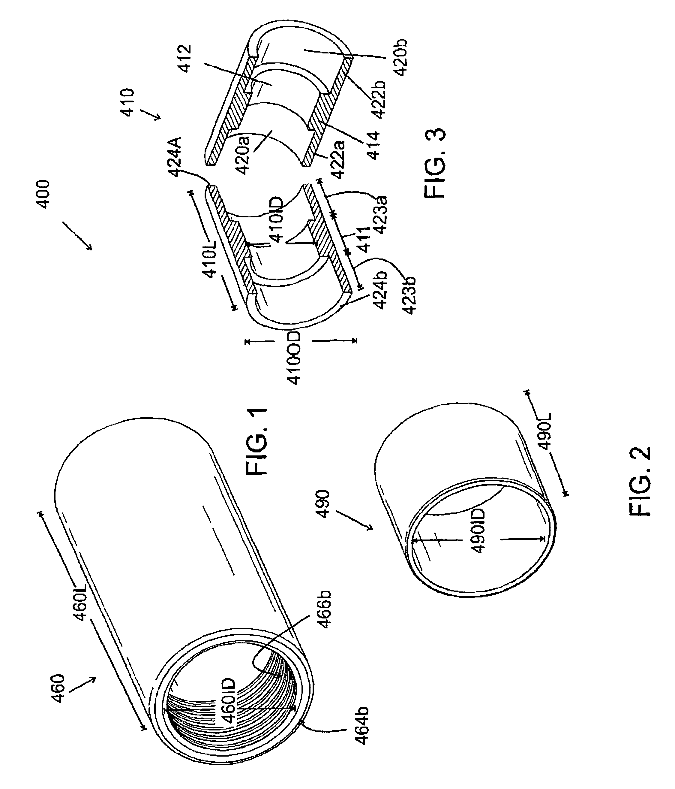
[0022]The illustrated invention is a conductive connector 400. As shown in FIG. 3, the conductive connector 400 includes a pair of intermediate halves 410 of a longitudinally split open-ended cylinder having a split-cylinder length 410L, and a split-cylinder outside diameter 410OD. Each intermediate half has a semi-cylindrical wall with a thicker center wall 412 having a center wall thickness 414, a center smaller inside diameter 410ID, and a center wall length 411. The center wall 412 has a pair of flanking walls 420a,420b where the pair of flanking walls 420a,420b bookend the center wall 412. Each flanking wall has a length 423a,423b and a thickness 422a,422b; where the flanking wall thicknesses 422a,422b are thinner than the thickness 414 of the center wall 412, such that the flanking walls 420a,420b are thinner than the center wall 412. The pair of intermediate halves is designed to simultaneously electrically tap two or more of the exposed layers of the inner conductor of the c...


PUM

PropertyMeasurementUnit
temperaturesaaaaaaaaaa
sectional lengthaaaaaaaaaa
lengthaaaaaaaaaa

Abstract

A connector anchors as outer conductor onto a cable and connects the outer conductor to the cable's inner conductor without exposing the inner conductor to the ambient environment. The connector includes a longitudinally split cylinder having a thicker center wall and a pair of flanking walls that wrap around a notched section of the cable and contact the inner conductor. An inner ring with multiple recessed interior circumferential grooves wraps around and overlaps the split cylinder so that the grooves will emboss and grip the cable's jacket without piercing the jacket when swaged. The outer conductor is placed over the inner ring. An outer ring anchors the outer conductor to the inner ring when swaged.

Description

STATEMENT OF GOVERNMENT INTEREST[0001]The invention described herein may be manufactured and used by or for the Government of the United States of America for Governmental purposes without the payment of any royalties.FIELD OF THE INVENTION[0002]The present invention relates generally to a swaged-on connector, and, in particular, to a conductive connector for electrically tapping an inner conductor of a mine sweeping cable to provide an electrical connection to an outer conductor, and simultaneously coaxially anchoring the outer conductor to the cable.BACKGROUND OF THE INVENTION[0003]Magnetic influence minesweeping cables create magnetic fields in the areas around the cables in order to cause magnetic influence mines deployed in a marine environment to explode prematurely, i.e., without damaging a ship. The magnetic field is typically created by a pair of exposed oppositely-charged conductors—a forward electrode and an aft electrode—that comprise parts of a cable being towed behind ...

Claims


Application Information

Patent Timeline
Patent Type & Authority Patents(United States)
IPC IPC(8): H01B7/28B63G7/04
CPCH01B7/2806B63G7/04H01B3/445
Inventor SOVEL, JAMES E.CORNMAN, JACOBGERSHENSON, MEIR
Owner USA REPRESENTED BY THE SEC OF THE NAVY
Learn More