
Controller for actuating a micromechanical actuator, actuating system for actuating a micromechanical actuator, micro-mirror system and method for actuating a micromechanical actuator

a micromechanical actuator and control system technology, applied in the field of controllers for actuating micromechanical actuators, can solve the problems of large system bandwidth, large computing power consumption, and negative impact on the quality of the image projected, and achieve the effects of flexible adaptability low complexity of the first controller element, and simple implementation

Active Publication Date: 2016-04-12
ROBERT BOSCH GMBH
View PDF4 Cites 1 Cited by
  • Summary
  • Abstract
  • Description
  • Claims
  • Application Information

AI Technical Summary

Benefits of technology

This approach minimizes resonance modes, adapts system bandwidth, and simplifies controller design, enabling efficient integration into ICs while maintaining image quality and reducing the need for buffer memory in projectors.

Problems solved by technology

In particular, the excitation of spurious modes has a negative impact on the quality of the image projected.
All controllers used have in common that they need a very large system bandwidth and thus require a very high amount of computing power.
Furthermore, some of the known controller concepts require additional status information of the MEMS mirror which may actually only be determined with great difficulty or which is very difficult to estimate.
Large system bandwidth and high computing power mean a large space requirement in the IC control integrated circuits, for example, for analog-digital converters, microcontrollers, digital-analog converters, driver stages and the like.

Method used


Image

  • Controller for actuating a micromechanical actuator, actuating system for actuating a micromechanical actuator, micro-mirror system and method for actuating a micromechanical actuator
  • Controller for actuating a micromechanical actuator, actuating system for actuating a micromechanical actuator, micro-mirror system and method for actuating a micromechanical actuator
  • Controller for actuating a micromechanical actuator, actuating system for actuating a micromechanical actuator, micro-mirror system and method for actuating a micromechanical actuator

Examples


Embodiment Construction

[0054]In all figures, identical or functionally equivalent elements and devices were denoted by the same reference numerals, unless indicated otherwise.

[0055]A micromechanical actuator is to be understood within the scope of this patent application as an actuator which is made of very small mechanical structures which may be actuated electrically. Such actuators are also known under the term MEMS (micro-electrical-mechanical-system).

[0056]A possible micromechanical actuator is, for example, a so-called micro-mirror. Micro-mirrors are, for example, used in video projectors to project the light of a light source line by line onto a screen.

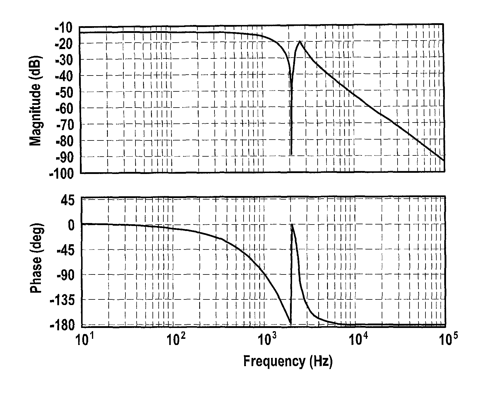
[0057]To be able to use such a micro-mirror in a video projector it is necessary to control exactly the deflection of the micro-mirror. Knowledge of the transfer function of such a micro-mirror is required for an exact control. It may, for example, be the following:

[0058]G⁡(s)=(1(2*pi*f⁢⁢02⁢⁢b)2*s2+2*D⁢⁢02⁢⁢b2*pi*f⁢⁢02⁢⁢b*s+1)*ks⁢⁢02*ks⁢⁢01ks⁢⁢03*(1(...


PUM


Abstract

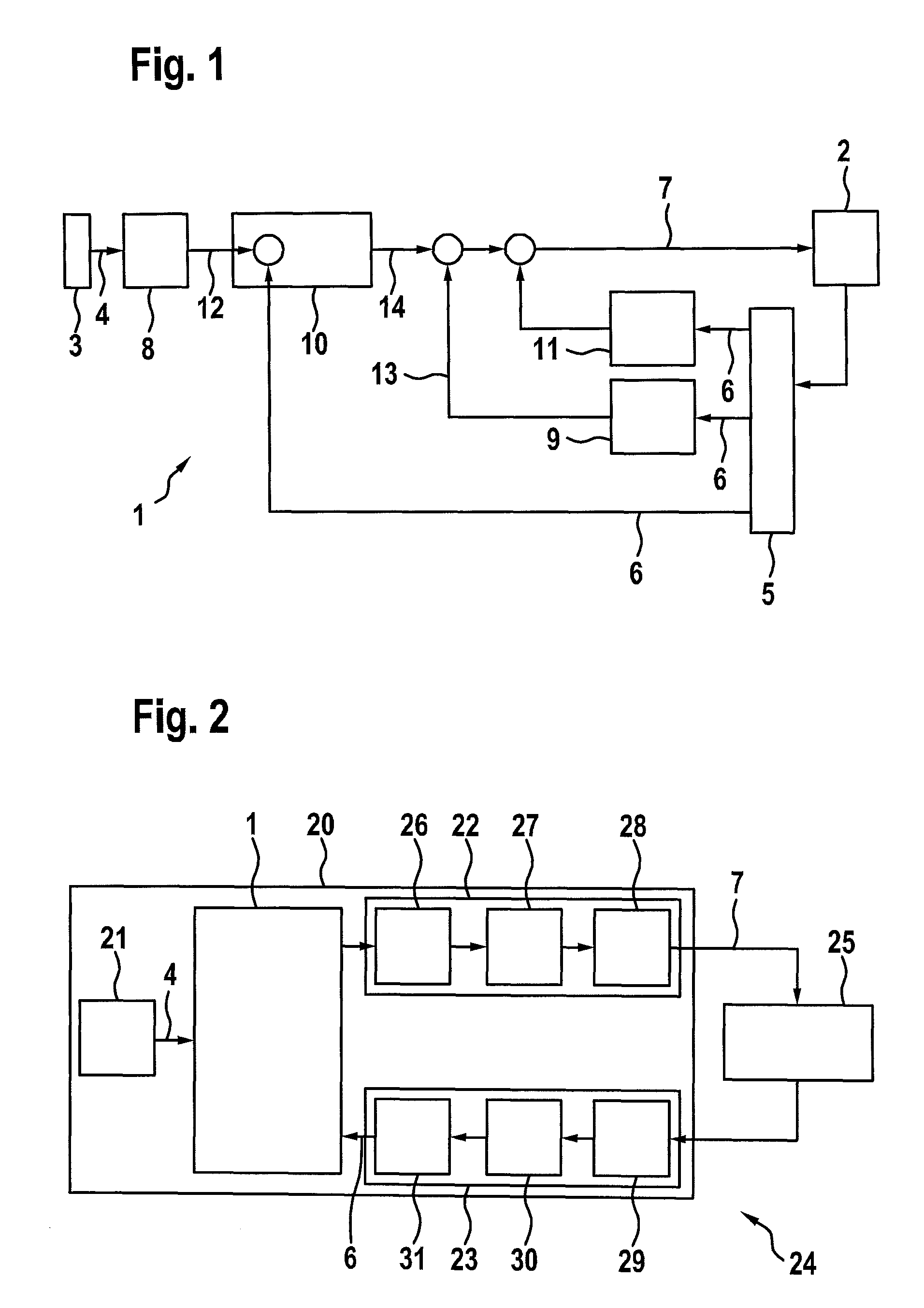
A controller for actuating a micromechanical actuator, including a first signal input which is designed to receive a reference signal, a second signal input which is designed to receive a measuring signal which denotes a recorded response by the micromechanical actuator to a control signal, a first controller element which is designed to filter and / or to attenuate predefined frequency modes and / or predefined frequency components in the received reference signal and to output a filtered and / or attenuated reference signal, a second controller element which is designed to modify the received measuring signal in order to minimize the quality of the first mode of the received measuring signal and to output a modified measuring signal, a third controller element which is designed to minimize the deviation between the filtered and / or attenuated reference signal and the received measuring signal and to output a minimized reference signal, a fourth controller element which is designed to modify the bandwidth of the received measuring signal and to subtract it from the minimized reference signal, which makes up the control signal. Furthermore, a corresponding actuating system, a corresponding micro-mirror system and a corresponding method are described.

Description

FIELD OF THE INVENTION[0001]The present invention relates to a controller for actuating a micromechanical actuator, to an actuating system for actuating a micromechanical actuator, to a micro-mirror system and to a method for actuating a micromechanical actuator.BACKGROUND INFORMATION[0002]Micromechanical actuators are used in a plurality of applications today. For example, micro-mirrors are utilized in projector units which are to be set up in a very small installation space.[0003]In such projector units, micro-mirrors are usually utilized which represent a so-called MEMS, i.e., micro electro mechanical system. These types of MEMS mirrors often have several mechanical resonance points which may be correspondingly electrically excited and which are also known as modes or poles in the transfer function. Furthermore, such MEMS mirrors also have anti-resonance modes which are also known as zero points in the transfer function or notch.[0004]The modes of the MEMS mirrors are subdivided ...

Claims


Application Information

Patent Timeline
Patent Type & Authority Patents(United States)
IPC IPC(8): G02B26/08
CPCG02B26/0841
Inventor WENZLER, AXELIYAD AL DIBS, MOHAMAD
Owner ROBERT BOSCH GMBH
Learn More