
Fiber optic connectors employing moveable optical interfaces with fiber protection features and related components and methods

a technology of fiber protection features and fiber optic connectors, applied in the field of fiber optic connectors, can solve the problems of fiber wear, bending or fatigue of the optical fibers within the fiber optic connector, attenuation or optical fiber damage, etc., and achieve the effect of preventing optical fiber attenuation and/or damage to the end portions

Active Publication Date: 2016-04-05
CORNING OPTICAL COMM LLC
View PDF64 Cites 11 Cited by
  • Summary
  • Abstract
  • Description
  • Claims
  • Application Information

AI Technical Summary

Benefits of technology

The patent text describes fiber optic connectors with movable optical interfaces that can be extended for cleaning and retracted for optical connection. To prevent damage, the connectors have features to protect the optical fibers. The method also involves disposing a separation plate to separate the end portions of the optical fibers. The technical effect of this invention is to provide longer life and secure mechanical connections for optical devices with movable optical interfaces.

Problems solved by technology

A more secure fiber optic connection permits a better optical connection by ensuring that fiber optic connection is properly aligned between the lenses of the connector and the optical device but current techniques of a movable optical interface result in fiber wear, bending or fatigue of the optical fibers within the fiber optic connector.
The wear, bending or fatigue may cause attenuation or optical fiber damage.

Method used


Image

  • Fiber optic connectors employing moveable optical interfaces with fiber protection features and related components and methods
  • Fiber optic connectors employing moveable optical interfaces with fiber protection features and related components and methods
  • Fiber optic connectors employing moveable optical interfaces with fiber protection features and related components and methods

Examples


Embodiment Construction

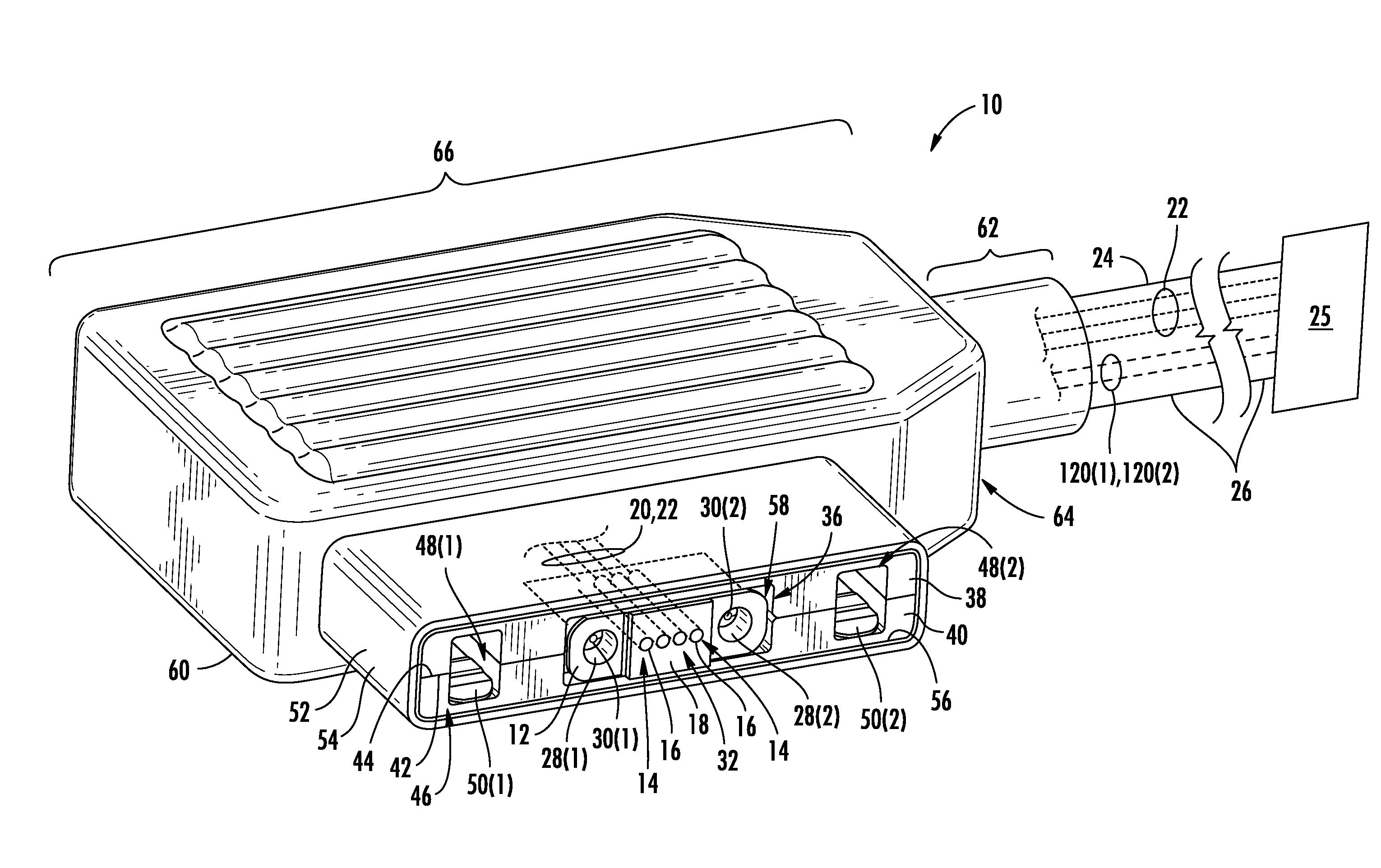
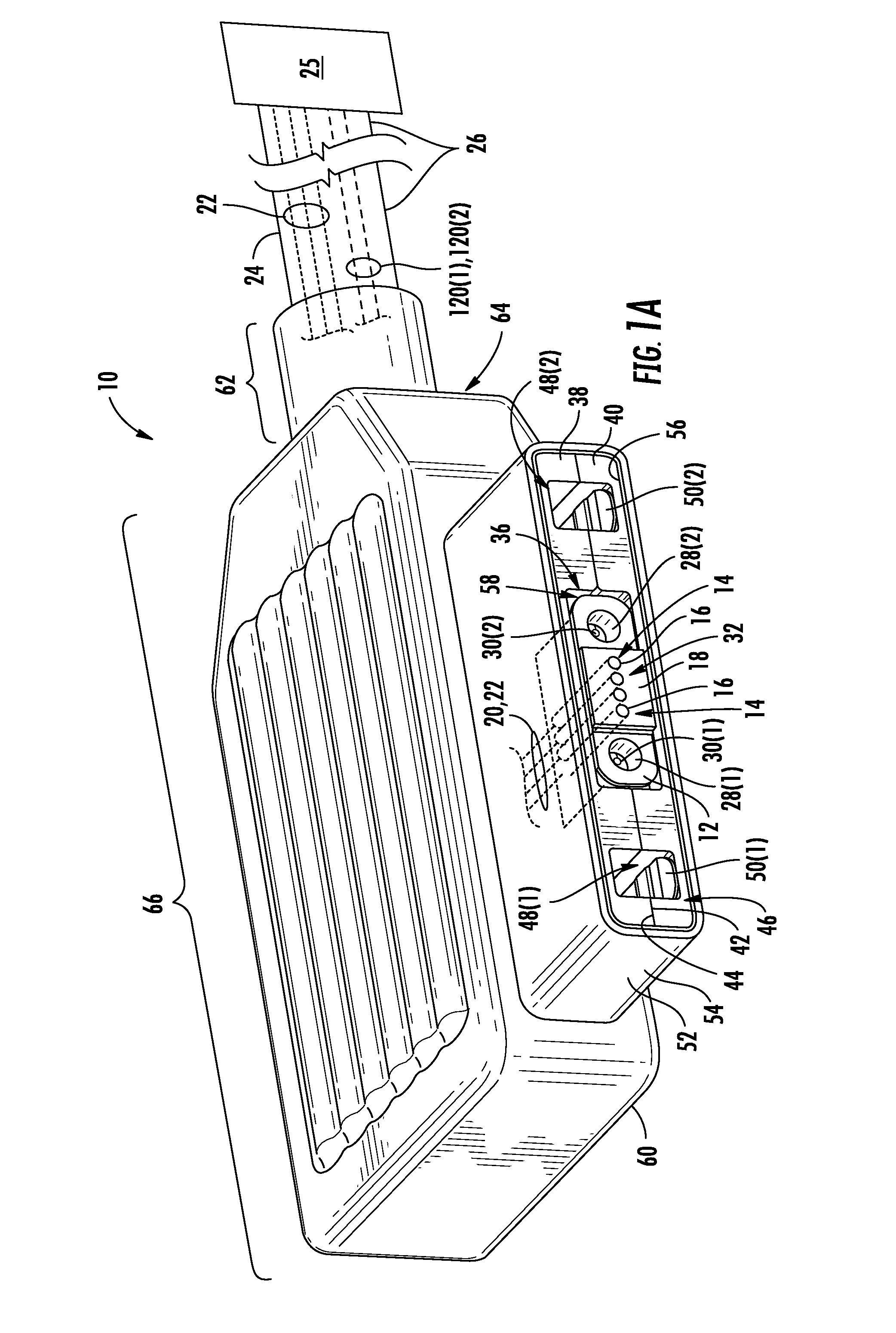
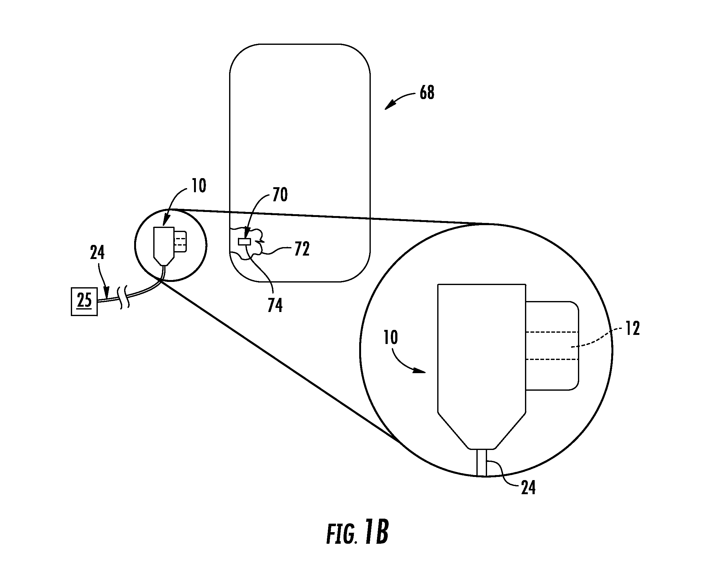
[0006]Embodiments disclosed herein include fiber optic connectors employing movable optical interfaces with fiber protection features and related components and methods. In one embodiment, the movable optical interface moves between an extended position for cleaning by the user of the movable optical interface and a retracted position to optically connect the fiber optic connector to an optical device in a mechanically-secure manner. Because the fiber optic cable employs the movable optical interfaces, embodiments described herein involve one or more fiber protection features to prevent optical fiber attenuation and / or damage to the end portions of the optical fibers.

[0007]In this regard, in one embodiment, a fiber optic connector is disclosed. The fiber optic connector may include a fiber optic connector body comprising a ferrule opening, a fiber optic cable opening, and an internal chamber. The fiber optic connector may also include a movable optical interface configured to move w...


PUM

PropertyMeasurementUnit
distanceaaaaaaaaaa
angleaaaaaaaaaa
angleaaaaaaaaaa

Abstract

Embodiments disclosed herein include fiber optic connectors employing a movable optical interface connected by optical fibers to a fiber optic cable, components and methods. In one embodiment, the movable optical interface moves between an extended position for cleaning by the user of the movable optical interface and a retracted position to optically connect the fiber optic connector to an optical device in a mechanically-secure manner. Because the fiber optic cable employs the movable optical interfaces, embodiments described herein involve one or more fiber protection features to prevent optical fiber attenuation and / or damage to the end portions of the optical fibers.

Description

BACKGROUND[0001]1. Field of the Disclosure[0002]The technology of the disclosure relates to fiber optic connectors having movable optical interfaces supporting optical fiber(s) for making connections with device(s).[0003]2. Technical Background[0004]Benefits of optical fiber include extremely wide bandwidth and low noise operation. Because of these advantages, optical fiber is increasingly being used for a variety of applications, including but not limited to broadband voice, video, and data transmission. Fiber optic networks employing optical fiber are being developed and used to deliver voice, video, and data transmissions to subscribers over both private and public networks. These fiber optic networks often include separated connection points linked by optical fibers to provide “live fiber” from one connection point to another connection point. Typically, the optical fibers are terminated in connectors for allowing optical connectivity. As consumer devices evolve they will transm...

Claims


Application Information

Patent Timeline
Patent Type & Authority Patents(United States)
IPC IPC(8): G02B6/36G02B6/38
CPCG02B6/3885G02B6/3829G02B6/3821G02B6/3853Y10T29/49826G02B6/38875G02B6/3823G02B6/3866
Inventor ISENHOUR, MICAH C.KNECHT, DENNIS M.LUTHER, JAMES P.
Owner CORNING OPTICAL COMM LLC
Learn More