
Apparatus for examining test bodies

a technology for test bodies and apparatuses, applied in the field of apparatus for examining test bodies, can solve the problems of reducing the power requirement of the drive of the movement unit, and affecting the operation of the instrumen

Inactive Publication Date: 2016-04-05
NORDSON CORP
View PDF22 Cites 0 Cited by
  • Summary
  • Abstract
  • Description
  • Claims
  • Application Information

AI Technical Summary

Benefits of technology

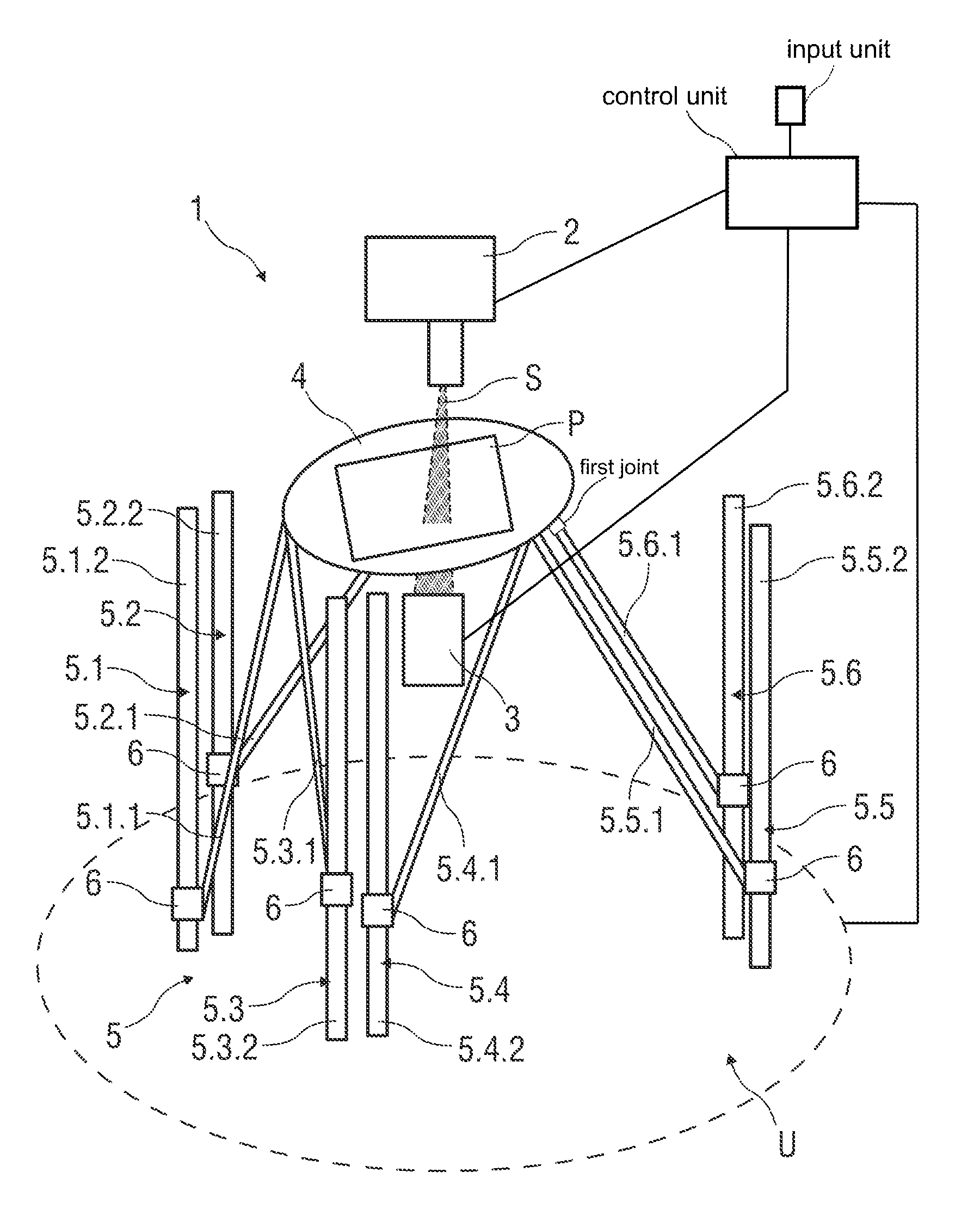
[0016]The construction of the movement unit as a parallel-mechanism movement unit particularly advantageously makes it possible for the test body to be arranged and aligned freely in various positions. Thus, the test body can be positioned freely in various test windows, as they are known, and detected by means of the detection unit. In addition, the apparatus according to the invention permits flexible and precise movement of the holding element and thus of the test body with efficient fabrication possibilities.
[0031]The at least one control unit is preferably coupled to at least one input unit for the pre-definition of a respective direction of movement of the movement unit, which permits simple pre-definition of the movement and / or positioning of the test body that is to be realized.

Problems solved by technology

This means that the improvement of one of the parameters leads to restrictions of the other parameters.
In addition, the parallel-mechanism movement unit, in particular as compared with serial mechanisms, the production of which is particularly complicated on account of difficult scalability and a high expenditure of energy, can be scaled simply in design terms, mechanically, in control engineering terms and productively.
On the other hand, in particular on account of the axis design, serial-movement mechanisms have significantly higher masses, which, during acceleration and braking, have a detrimental effect on the latter and place a high power requirement on a drive of the movement unit.

Method used


Image

  • Apparatus for examining test bodies
  • Apparatus for examining test bodies

Examples


Embodiment Construction

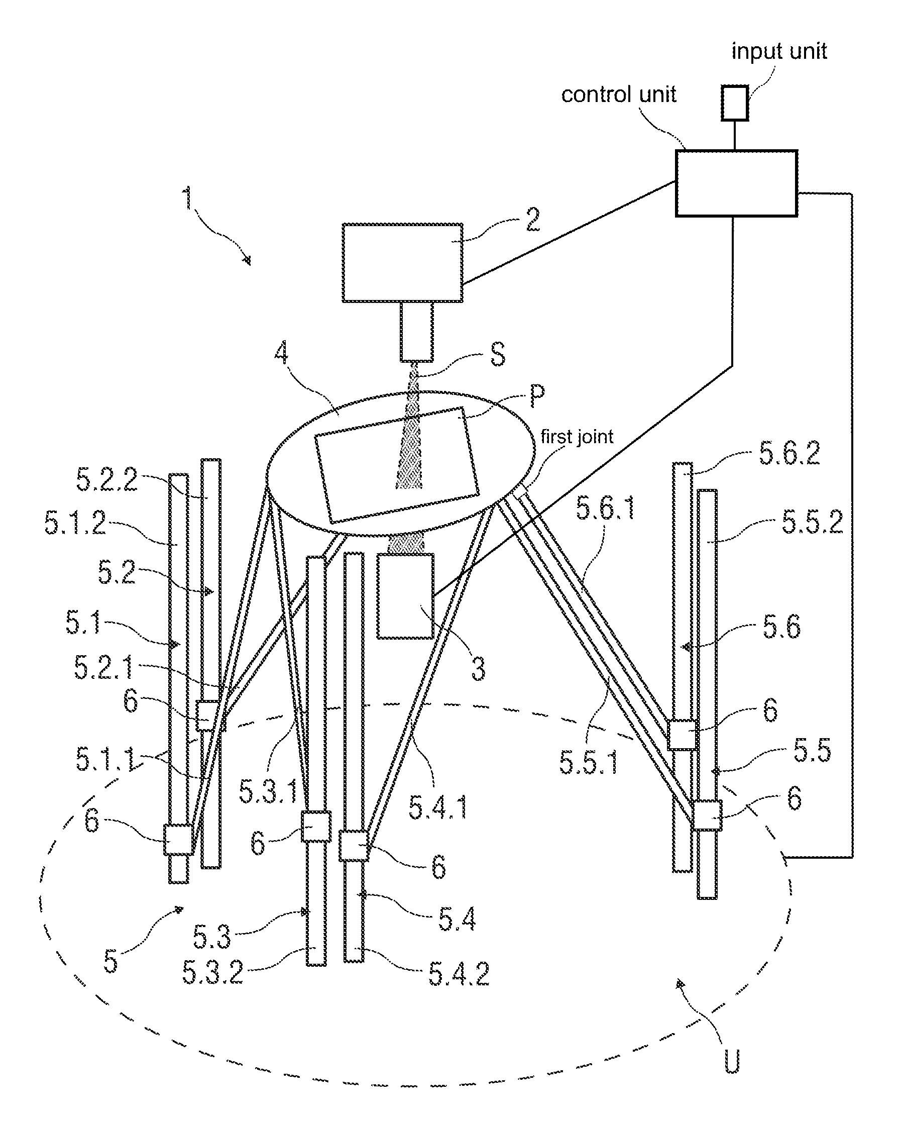
[0034]The single FIG. 1 shows a possible exemplary embodiment of the apparatus 1 according to the invention for examining test bodies P. The test body P in the exemplary embodiment illustrated is a printed circuit board. As distinct therefrom, the examination of further electronic subassemblies and electronic devices is also possible.

[0035]The apparatus 1 comprises a radiation source 2 constructed as an X-ray source for X-raying the test body P. Also provided is a detection unit 3 formed as an imaging detection unit for detecting radiation S emitted by means of the radiation source 2.

[0036]Arranged between the radiation source 2 and the detection unit 3 is a holding element 4, which is formed from a carbon fiber composite material that is transparent to the X-rays, in order to hold the test body P and position the latter between the radiation source 2 and the detection unit 3.

[0037]A movement unit 5 for moving the holding element 4 is coupled to the holding element 4. The movement u...


PUM

PropertyMeasurementUnit
angleaaaaaaaaaa
angle of inclinationaaaaaaaaaa
transparentaaaaaaaaaa

Abstract

The invention relates to an apparatus (1) for examining test bodies (P), in particular electronic subassemblies and electronic devices, comprising at least one radiation source (2) for X-raying at least one test body (P), at least one detection unit (3) for detecting radiation (S) emitted by means of the radiation source (2), at least one holding element (4) for holding the at least one test body (P) and for positioning the latter between the radiation source (2) and the detection unit (3), and a movement unit (5), coupled to the holding element (4), for moving the holding element (4), wherein the movement unit (5) is constructed as a parallel-mechanism movement unit.

Description

CROSS-REFERENCE TO RELATED APPLICATIONS[0001]This application claims priority to German application no. DE 10 2012 216 687.4 filed on Sep. 18, 2012, which is hereby incorporated by reference in its entirety.BACKGROUND[0002]1. Field of the Invention[0003]The invention relates to an apparatus for examining test bodies, in particular electronic subassemblies and electronic devices.[0004]2. Background Art[0005]Known from the prior art are various apparatuses for examining test bodies, in particular electronic subassemblies and electronic devices.[0006]Furthermore, what are known as manipulators for positioning objects in space are known from the prior art. These manipulators make it possible to position an object with different degrees of freedom. The manipulators are constructed as industrial robots, hexapods or what are known as multi-axis table or portal systems. Furthermore, the manipulators are differentiated with respect to their mechanisms into serial manipulators, such as robots...

Claims


Application Information

Patent Timeline
Patent Type & Authority Patents(United States)
IPC IPC(8): G01N23/04G01N23/08G01N23/083G01N23/087G01N23/02
CPCG01N23/083G01N23/02G01N23/04G01N23/08G01N23/087G01N23/06
Inventor RIMBACH, JANRIMBACH, KIRKE
Owner NORDSON CORP
Learn More