
Electrical switching device, notably for direct current, equipped with a magnetic module for blowing the electric arc

a technology of electric switching device and magnetic module, which is applied in the direction of air-break switch, contact, electrical apparatus, etc., can solve the problems of affecting the control of electric arcs, causing damage, and not being able to achieve the purpose of the devi

Active Publication Date: 2016-03-29
SOCOMEC
View PDF4 Cites 9 Cited by
  • Summary
  • Abstract
  • Description
  • Claims
  • Application Information

AI Technical Summary

Benefits of technology

The present invention offers a switching device with a special magnetic module designed to blow the electric arc in cases of electrical contacts operating in a breaking plane. This module provides reliability and efficiency in controlling the electric arc, regardless of the direction of connection or the polarity of the module. It simplifies the manufacturing process, reduces costs, and increases the disconnecting capabilities of the device, making it either more powerful or smaller for the same disconnection voltage.

Problems solved by technology

If this is not the case, the purpose would not be achieved.
However, according to the polarity of the magnets with respect to the electrical circuit, the electric arcs generated by the two parallel push contacts and moved by these permanent magnets may interfere with each other and build up between other components of the switching device, where they might create damages.
On the other hand, the permanent magnets are very close to each other and their respectively produced magnetic fields may interfere with each other, which may penalize the control of the electric arcs.
So, the disconnection management of such a device is not optimal.

Method used


Image

  • Electrical switching device, notably for direct current, equipped with a magnetic module for blowing the electric arc
  • Electrical switching device, notably for direct current, equipped with a magnetic module for blowing the electric arc
  • Electrical switching device, notably for direct current, equipped with a magnetic module for blowing the electric arc

Examples


Embodiment Construction

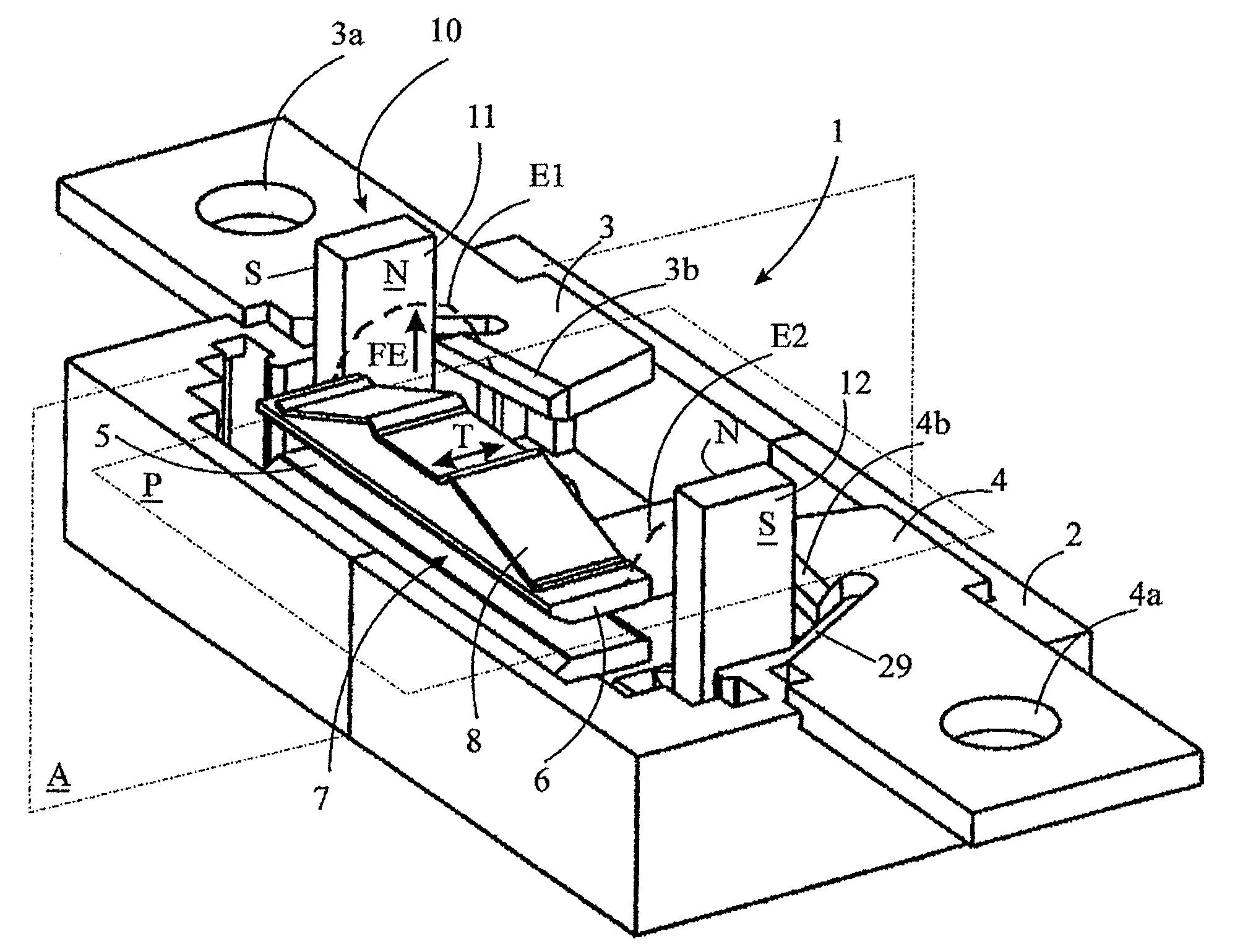
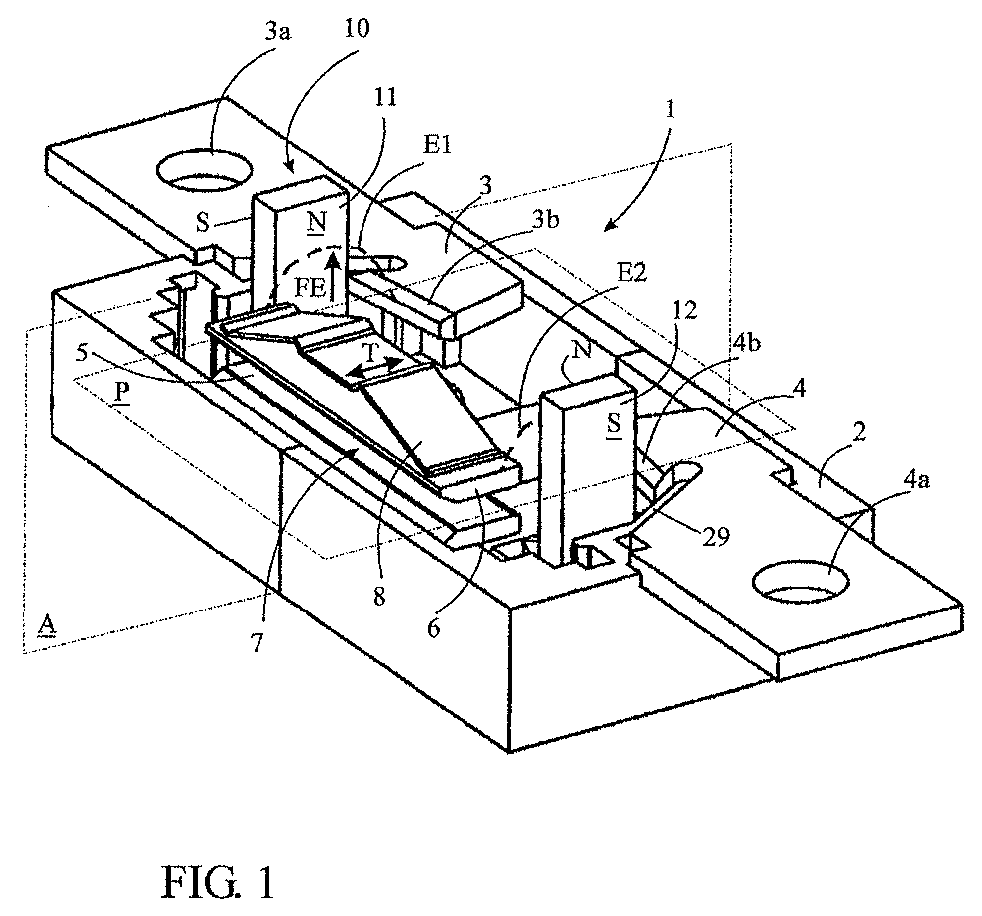
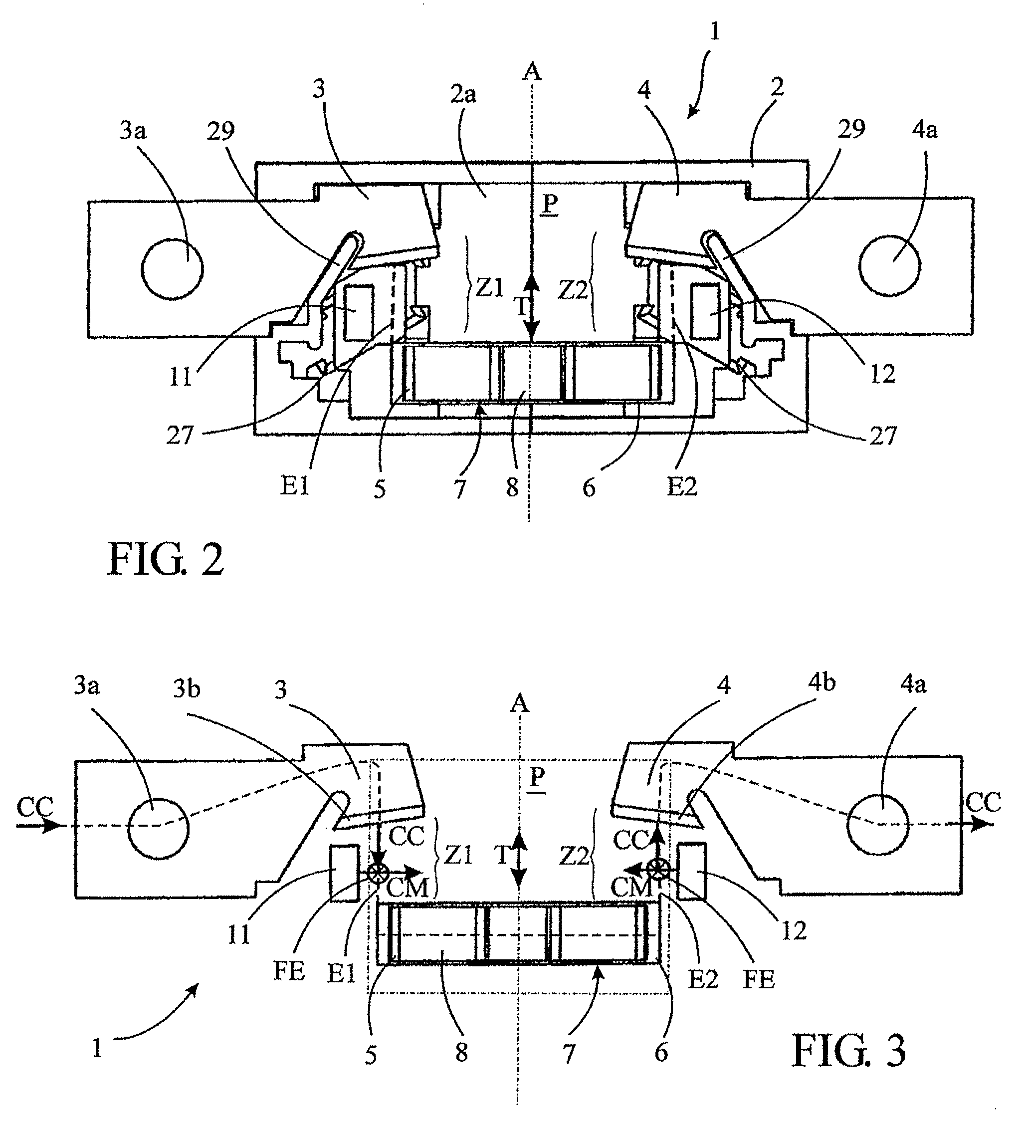
[0004]The present invention aims to overcome these disadvantages by offering a switching device equipped with a magnetic module specially designed and adapted for blowing the electric arc in the case of electrical contacts operating in a breaking plane, providing a reliability and efficiency in the control of the electric arc that are totally independent of the polarity of the magnetic module and of the direction of connection of said switching device to an external electrical circuit, allowing to simplify and to reduce the manufacturing costs of such switching device, but also to increase notably its disconnecting capabilities, which allows either to increase the disconnection voltage for a switching device with the same size or to reduce the size of said device for the same disconnection voltage.

[0005]To that purpose, the invention relates to a switching device of the kind stated in the preamble, characterized in that said magnetic module comprises a first permanent magnet housed ...


PUM


Abstract

An electrical switching device (1) which comprises at least one double breaking pole provided with two fixed contacts (3, 4) that cooperate with two moving contacts (5, 6) arranged so as to move in a breaking plane (P) and define, with every fixed contact, a breaking zone. The device comprises a permanent magnet (11, 12) housed in an insulating holder arranged in the immediate environment, next to each breaking zone, symmetrically with respect to the breaking plane and oriented so as to generate a magnetic excitation vector parallel to the breaking plane (P) so that the induced electromagnetic force (FE) moves and stretches every electric arc (E1, E2), generated when opening the electrical circuit, in a direction perpendicular to the breaking plane (P), leading to the extinction of the electric arc regardless of the polarity of the magnet and / or of the current.

Description

TECHNICAL SCOPE[0001]The present invention relates to an electrical switching device, notably for direct current, equipped with a magnetic module for blowing the electric arc, said switching device including at least a housing that delimits at least one breaking pole comprising at least one first fixed contact that cooperates with at least one first moving contact, said moving contact being arranged so as to move in a plane called breaking plane and to define with said first fixed contact a first breaking zone in which a first electric arc extends when opening the electrical circuit.PRIOR ART[0002]Electrical switching devices comprising a magnetic module contributing to the control of the electric arc generated when opening the electrical circuit are already known. In most of the cases, these switching devices comprise at least one splitting chamber for the electric arc and the magnetic module comprises at least one permanent magnet arranged so as to blow magnetically the electric a...

Claims


Application Information

Patent Timeline
Patent Type & Authority Patents(United States)
IPC IPC(8): H01H9/44H01H1/20H01H33/59
CPCH01H9/443H01H1/2041H01H33/596
Inventor COQUIL, KARINEHERTZOG, JEROME
Owner SOCOMEC
Learn More