
Hovering and gliding multi-wing flapping micro aerial vehicle

a multi-wing, micro-aerial technology, applied in the field of aerial vehicles, can solve the problems of fixed-wing mavs not being able to hover or fly backwards, affecting the range, endurance, operation altitude, etc., and reducing the amplitude of the flapping. , the effect of increasing the amplitude of the flapping actuator

Active Publication Date: 2016-03-22
GEORGIA TECH RES CORP
View PDF22 Cites 7 Cited by
  • Summary
  • Abstract
  • Description
  • Claims
  • Application Information

AI Technical Summary

Benefits of technology

The design enhances payload capacity, extends flight time, and improves maneuverability by reducing energy consumption and eliminating the need for tail rudders or elevators, enabling efficient hovering, gliding, and dynamic flight in six degrees of freedom.

Problems solved by technology

DARPA also places limits on, among other things, the range, endurance, operational altitude, maximum speed, maximum payload, and cost of manufacture.
Unlike conventional aerial vehicles, however, an MAV's small size and maneuverability can make it difficult to detect.
Fixed-wing MAVs cannot hover or fly backwards, however, and have a limited ability to fly at slow speeds.
Rotary-wing MAVs are generally inefficient, however, and so their maneuverability comes at the cost of shorter flight time and lower payload capacities.
The inefficiencies of presently known MAVs are due, at least in part, to aerodynamics.
These variances can cause inefficiencies if larger vehicles are simply scaled down to MAV size, or smaller.
For this reason, designing MAVs that can efficiently fly in this regime represents a unique and difficult challenge to design engineers.
In general, however, conventional VTOL capable vehicles do not efficiently scale down to the small sizes of MAVs.
This means that large VTOL capable vehicles cannot simply be reduced to MAV size and maintain high flight efficiencies.
Birds and insects therefore have unmatched maneuverability, speed, and agility.
However, all of these models lack appreciable flight time, appreciable payload capacity, the ability to fly in six degrees of freedom (i.e., hovering and VTOL capabilities).
The use of two wings limits the lifting power that can be generated while staying within the MAV sizing parameters.
In addition, in prior designs, the wings were not independently controlled.
Because the wings were not independently controlled, modifying the flapping amplitude and / or frequency of each individual wing was not possible.
Unlike many birds and insects, current designs do not utilize resonance to reduce the amount of energy needed to flap the wings.
This can be an inefficient way to produce and / or modify thrust.
For these reasons, known MAVs with flapping wings are inefficient, have low lifting power, and are overly complex.
Moreover, the inefficiencies and low lifting power associated with these MAVs require that they either have small power supplies that exhaust quickly, or be tethered to an external power supply.
Accordingly, while engineers have modeled MAVs after some birds and insects, there are many designs that have not yet been attempted.

Method used


Image

  • Hovering and gliding multi-wing flapping micro aerial vehicle
  • Hovering and gliding multi-wing flapping micro aerial vehicle
  • Hovering and gliding multi-wing flapping micro aerial vehicle

Examples


example 1

[0243]To test the under actuated system step response in simulation, an initial condition of φRef=−12°, θRef=11°, ψRef=11.5° is set and the MAV is commanded to maintain a 20 cm altitude. Initially, the system was tested with a manually selected constant PID gains. The results are shown in the FIGS. 34a-34e. The five graphs show pitch, roll, yaw, altitude and actuator thrust response versus time, respectively. As shown, settling time for manual selection was approximately 50-60 seconds, with an overshoot of approximately 4 degrees. As shown, due to the complexities in the system, manual gain control is less than ideal and requires extensive experimentation to set useful values.

[0244]In some embodiments, feedback type controllers can be used for improved performance. A Proportional-Integral-Derivative (“PID”) controller, for example, can be used. The three components of the PID controller can be tuned to optimize response time, overshoot, or a combination thereof. As discussed below, ...

example 2

[0248]To measure the effectiveness of the system 3500, the cost function for the GA 3510 can be defined as the cumulative area under the step response graph until the system 3500 settles to the commanded, or desired, value. In other words, the smaller the area under the curve, the faster the response time of the system 3500. Generally, to apply the GA 3510 to a selection problem, the gene structure and evaluation method should be prepared. In this case, for example, the set of PI gains 3520 can be defined as a gene and the fitness function can be defined as the cost metric. The crossover rates and the mutation rates are set as 100% and 10%, respectively. The cost function is the area sum under the response curves.

[0249]As shown in the Table 2 below and in FIGS. 36a-36c, there is a marked performance improvement using the GA based design tuning 3500 over manual gain selection 2900. The table highlights the results of gain tuning using the devised GA 3510 after 6 generations. As menti...

example 3

[0251]In some embodiments, a PD controller can be used. By removing the integral component, faster response times are possible, but some accuracy is sacrificed. Thus, while the system tends to settle to the reference position, in some cases it is slightly off. As with all control systems, accuracy, speed, and processor power can be balanced, as required, to meet, for example and not limitation, specific mission, cost, or design parameters.

[0252]In this example, the system was provided an initial set of gains and an initial deflection of 20-30 degrees with a reference position of zero degrees. As shown in FIGS. 36d and 36e, the output response is much faster than predicted in the simulation model for the PID controller or the PD Controller. As shown, response time for both pitch and roll is 1-1.5 seconds. Of course, these response times are significantly affected by several factors, including but not limited to, under or over actuation, vehicle and / or payload weight, wing span and sh...


PUM


Abstract

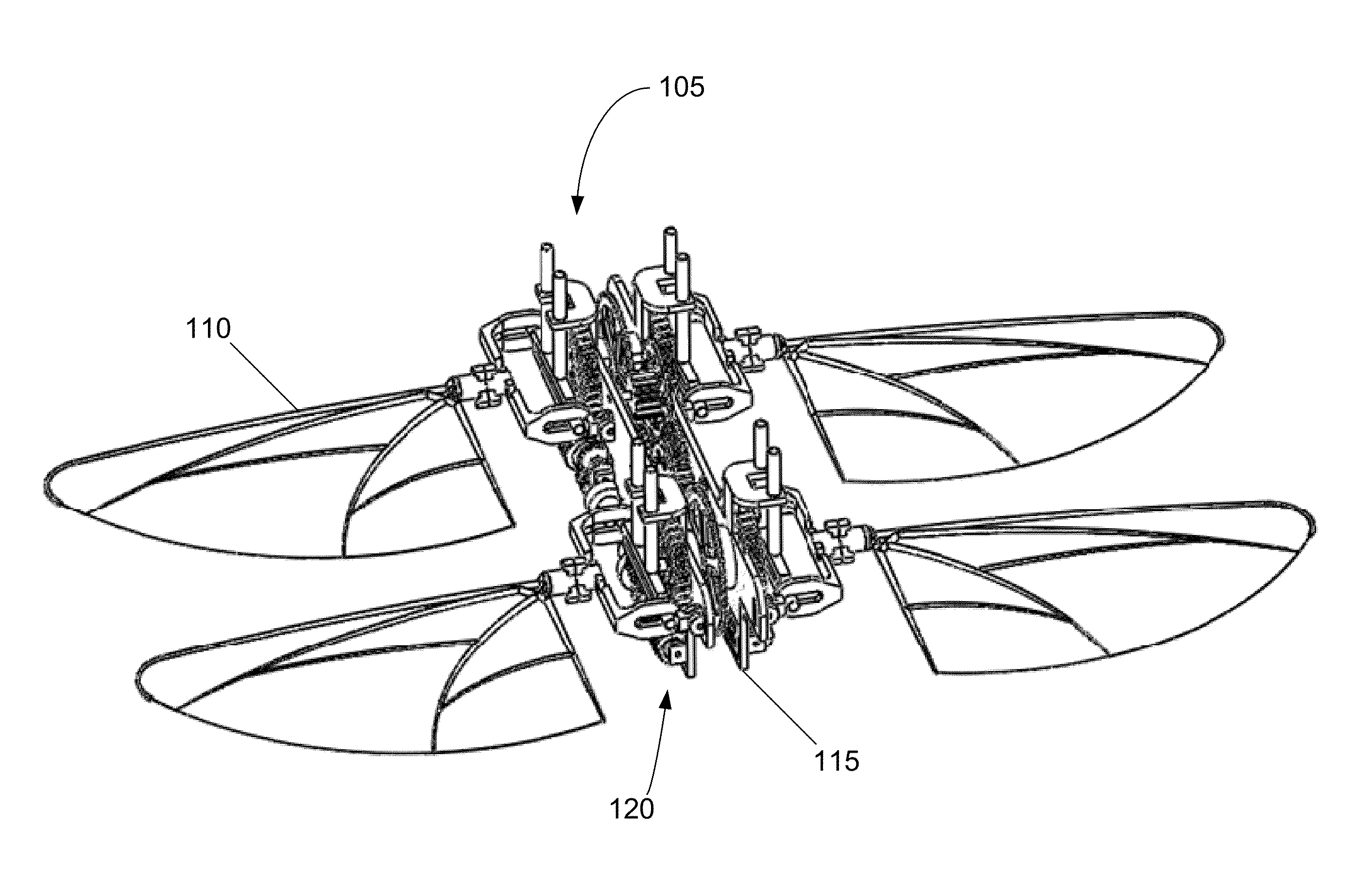
Multi-wing hovering and gliding flapping Micro Air Vehicles (“MAV”) are disclosed. The MAV can have independent wing control to provide enhance energy efficiency and high maneuverability. Power to each wing can be controlled separately by varying the amplitude of the wing flapping, the frequency of the wing flapping, or both. The flapping frequency can be controlled such that it is at or near the natural frequency of the wings for improved energy efficiency. The wings can be controlled by a gear train, coil-magnet arrangement or many other actuation systems that enable variable frequency flapping, variable amplitude flapping, or a combination of both. The gear train mechanism provides gyroscopic stability during flight. The wing flapping can include a rotation, or feathering motion, for improved efficiency. The wings can be transitioned between flapping flight and fixed wing flight to enable gliding and hovering in a single configuration.

Description

CROSS-REFERENCE TO RELATED APPLICATIONS[0001]This application claims the benefit of International Patent Application Serial No. PCT / US2012 / 025718, filed 17 Feb. 2012, and entitled “Hovering and Gliding Multi-Wing Flapping Micro Aerial Vehicle,” which claims the benefit of U.S. Provisional Patent Application Ser. Nos. 61 / 443,914, filed 17 Feb. 2011; 61 / 466,204, filed 22 Mar. 2011; 61 / 481,500, filed 2 May 2011; and 61 / 481,484, filed 2 May 2011. All of the above-referenced applications are incorporated herein by reference in their entireties as if fully set forth below.STATEMENT REGARDING FEDERALLY SPONSORED RESEARCH[0002]This invention was made with Government support under contract number FA9550-10-C-0036, awarded by the U.S. Air Force. The Government has certain rights in the invention.BACKGROUND OF THE INVENTION[0003]1. Field of the Invention[0004]The invention relates to the field of aerial vehicles, and in particular, to micro aerial vehicles with flapping wings.[0005]2. Descript...

Claims


Application Information

Patent Timeline
Patent Type & Authority Patents(United States)
IPC IPC(8): B64C33/00B64C33/02
CPCB64C33/025B64C33/02
Inventor RATTI, JAYANTJONES, EMANUELVACHTSEVANOS, GEORGE
Owner GEORGIA TECH RES CORP
Learn More