
Disposal of munitions

a technology for disposing munitions and ammunition, which is applied in the direction of ammunition, weapons, weapons, etc., can solve the problems of greater wall thickness on one side than on the other, and cannot be sure that the inner and outer walls of the shell are perfectly cylinders

Active Publication Date: 2016-03-15
DISARMCO
View PDF10 Cites 0 Cited by
  • Summary
  • Abstract
  • Description
  • Claims
  • Application Information

AI Technical Summary

Benefits of technology

[0014]The risk of detonating the explosive material is avoided in the present invention by virtue of the fact that the cutting tool does not penetrate into the inner chamber during the machining of the shell. There is therefore no risk of the explosive material being ignited by the sparks generated during the machining. Furthermore, any water used for lubrication and / or cooling during the machining does not mix with the explosive material and generate pink water.
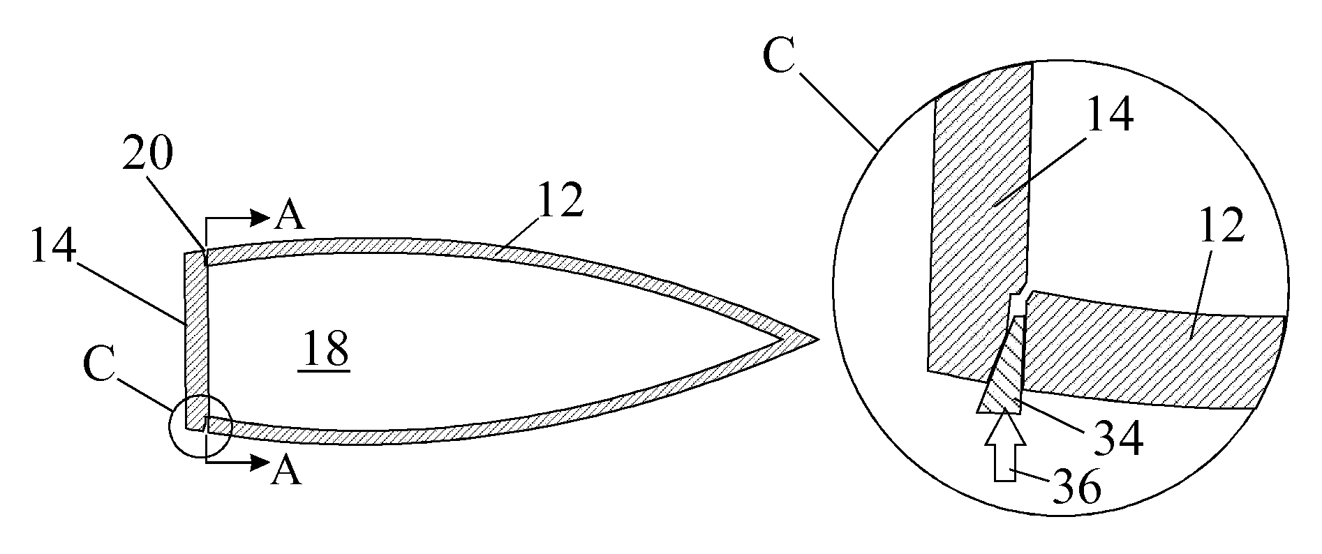
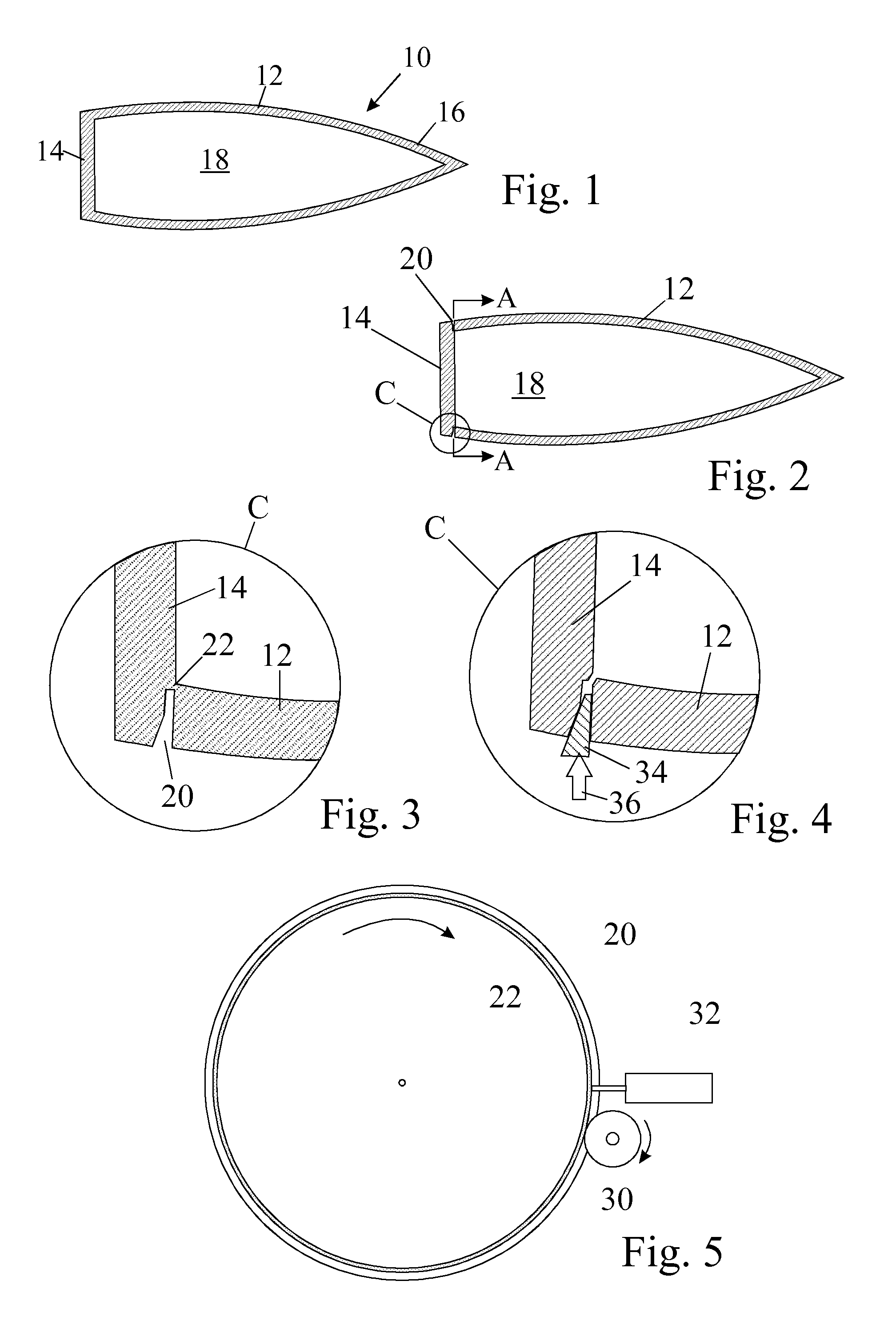
[0017]The positioning of the groove at the junction between the base and the cylindrical wall of the shell is also important in that it reduces the risk of sharp burrs, which should be avoided, especially on the cylindrical wall of the shell.
[0018]The greater the thickness of material that is left behind after machining of the groove, the less is the risk of accidentally penetrating the inner chamber but the greater will be the force required to prise the two parts of the shell apart. In practice, a compromise is reached in selecting the thickness of material remaining on the parting line after machining so that, allowing for measuring and machining tolerances, all risk of the inner chamber being penetrated is avoided, but the parts can still readily be prised apart using a suitable implement. In practice, it has been found that if one aims to leave behind a thickness of approximately 0.5 mm, the shell can be reliably cracked open without risk of penetration of the shell wall during machining.

Problems solved by technology

For example, if the shell is made of metal cast in a sand mould, one cannot be certain that the core of the mould was positioned centrally with high precision, which would result in the wall thickness being greater on one side than on the other.
One also cannot be sure that the inner and outer walls of the shell are perfectly cylinders, especially if the shells are rusty or if they have been subjected to stresses during transportation and storage.

Method used


Image

  • Disposal of munitions
  • Disposal of munitions

Examples


Embodiment Construction

)

[0027]A typical munition shell 10, as shown in section in FIG. 1, has a generally cylindrical outer wall 12, a tapering nose 16 and a flat base 14. The shell is hollow and has an inner chamber 18 filled with an explosive material. The cylindrical wall 12 has a wider girth near its centre than at its base.

[0028]The conventional manner of disposing of such a munition is to start by cutting open the shell and this is done by sawing through the wall of the shell at its point of maximum girth. This produces two shell parts both containing explosive. The two parts are emptied of explosive and the metal parts of the shell can then be recycled. The explosive can be destroyed by burning it, an operation that can be performed safely if the explosive is first suitably shredded.

[0029]As earlier described, regardless of the method used to cut through the shell wall, this results in the creation of pink water, which itself presents a disposal problem.

[0030]In the illustrated embodiment of the in...


PUM


Abstract

A method is described for safely opening the shell of a munition (10) having an inner chamber containing an explosive material. The method comprises the steps of machining a groove (20) into the shell along a parting line that encircles the outer surface of the munition and divides the shell into two parts. The groove (20) is of sufficient depth to weaken the shell but not to penetrate into the inner chamber of the munition. After machining the groove (20), the shell is cracked open by prising the two parts of the shell apart by inserting a suitable implement into the groove.

Description

FIELD OF THE INVENTION[0001]The present invention relates to the disposal of munitions and in particular to the opening of the shell of a munition so that the explosive material contained within it may be removed for safe destruction.BACKGROUND OF THE INVENTION[0002]It has previously been proposed to cut through the shell of a munition in order that its contents may be removed. One known method is to cut through the munition at its point of maximum girth using either a metal cutting implement or a water jet. Even when a metal cutting implement is used, the implement is normally lubricated with water and inevitably water comes into contact with the explosive material during the course of opening the shell and the water becomes contaminated.[0003]Water that is contaminated with explosive material, referred to as pink water, cannot safely be allowed to flow into drains or into nearby rivers and itself presents a disposal problem.[0004]DE 42 21 666 discloses a method of opening a muniti...

Claims


Application Information

Patent Timeline
Patent Type & Authority Patents(United States)
IPC IPC(8): F42B33/06
CPCF42B33/06
Inventor REID, JOHN
Owner DISARMCO
Learn More