
Monolithic LED chip in an integrated control module with active circuitry

a technology of led chip and integrated control module, which is applied in the direction of electroluminescent light source, electric lighting source, and use of semiconductors. performance of led array,

Active Publication Date: 2016-03-01
SIGNIFY HLDG BV
View PDF11 Cites 57 Cited by
  • Summary
  • Abstract
  • Description
  • Claims
  • Application Information

AI Technical Summary

Benefits of technology

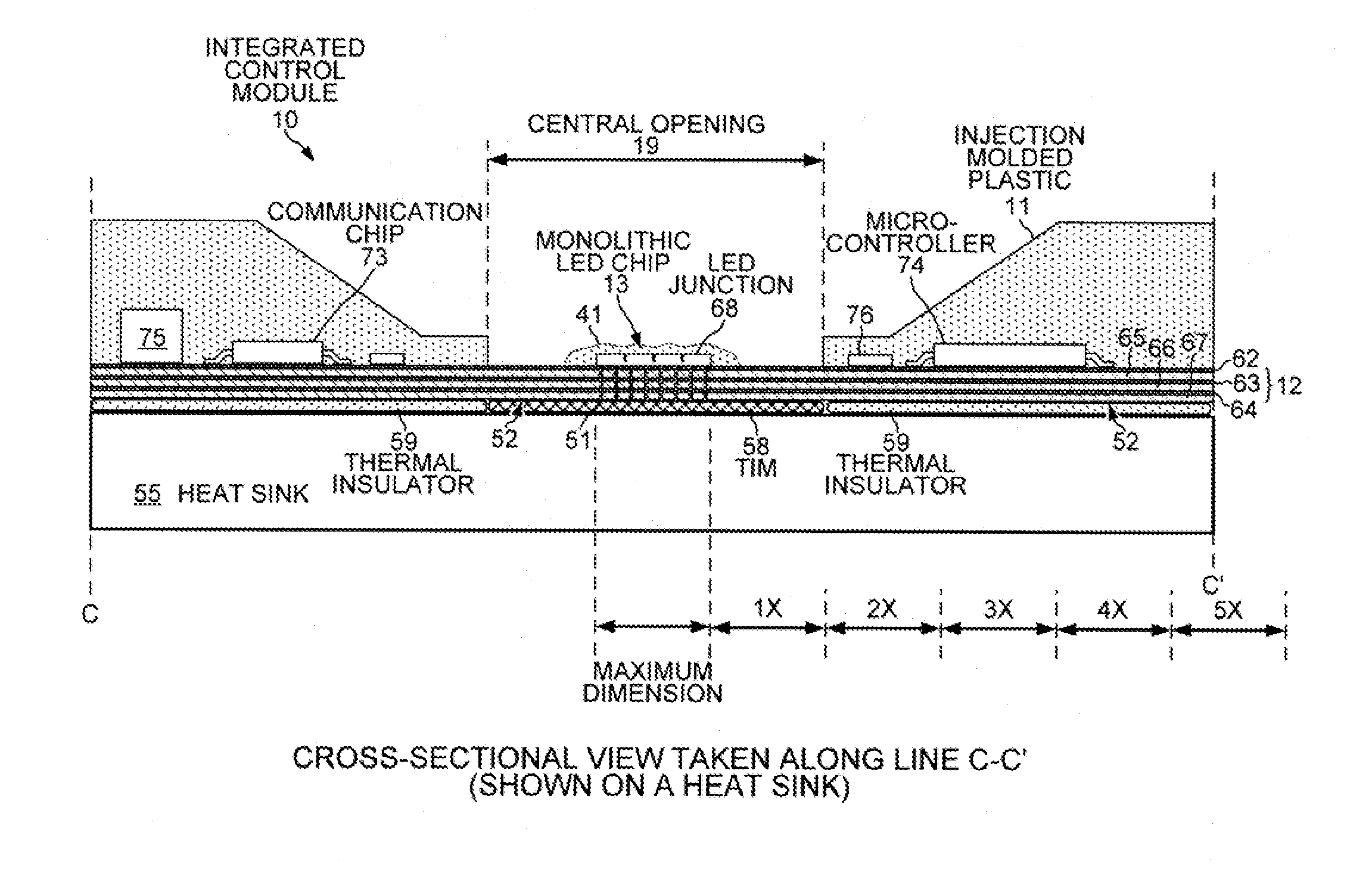
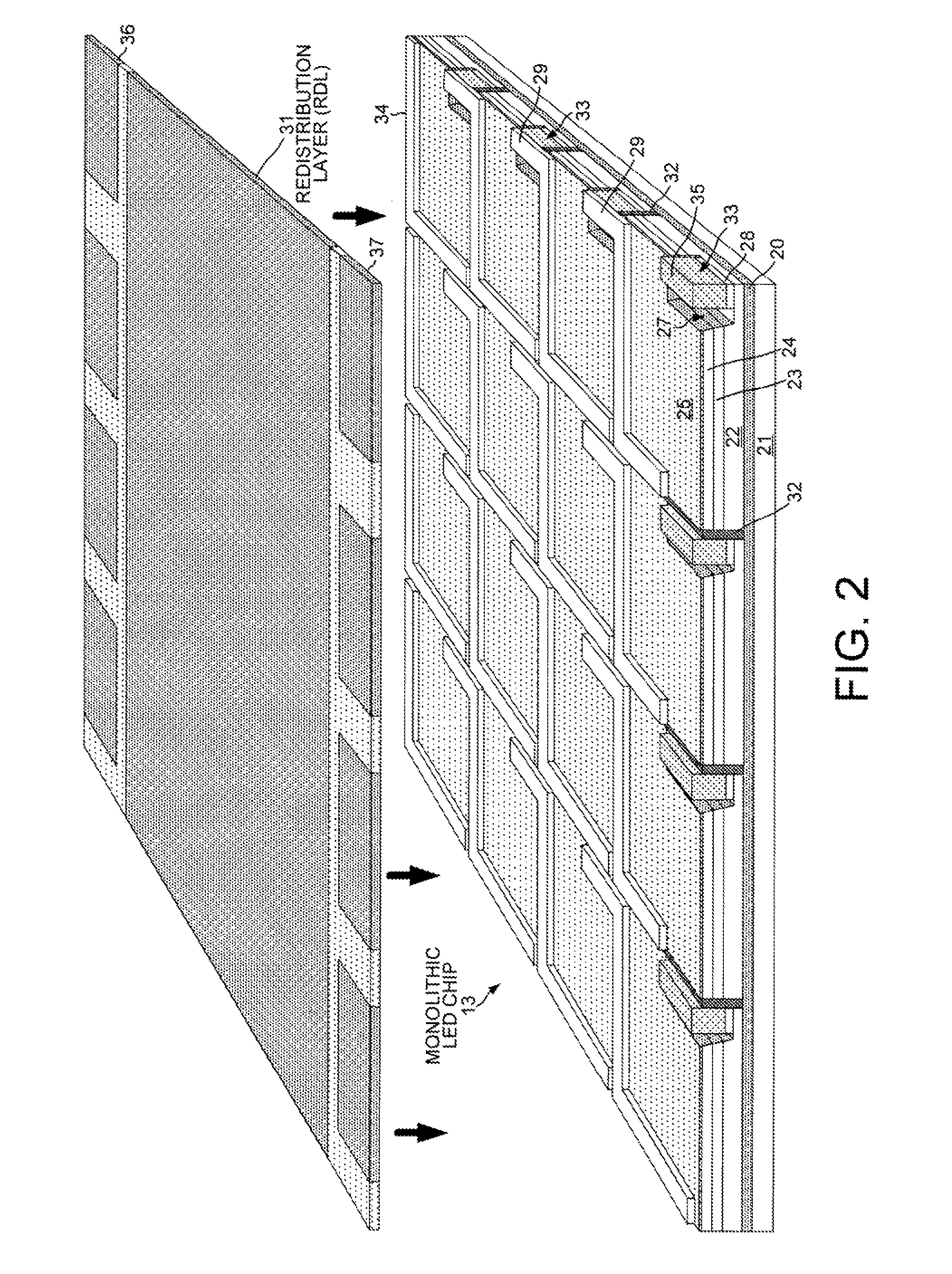
The patent describes a lighting device that includes a monolithic LED chip flip-chip mounted onto an interconnect structure. The chip has separate LED junctions that are controlled by an active electronic component. The device also has phosphor particles and a color sensor to measure the light emitted from the device. The device may include metallic vias to conduct heat away from the LED junctions, and a thermal insulator to prevent heat from affecting the active electronic component. The method involves using the temperature of one LED junction to determine the temperature of the chip. The patent aims to provide a more efficient and precise way to control the LED drive currents and measure the light emitted from a lighting device.

Problems solved by technology

If the temperature of the LED array is allowed to increase excessively, performance of the LED array may suffer and the LED array may actually fail.

Method used


Image

  • Monolithic LED chip in an integrated control module with active circuitry
  • Monolithic LED chip in an integrated control module with active circuitry
  • Monolithic LED chip in an integrated control module with active circuitry

Examples


Embodiment Construction

[0025]Reference will now be made in detail to examples and some embodiments of the invention, examples of which are illustrated in the accompanying drawings.

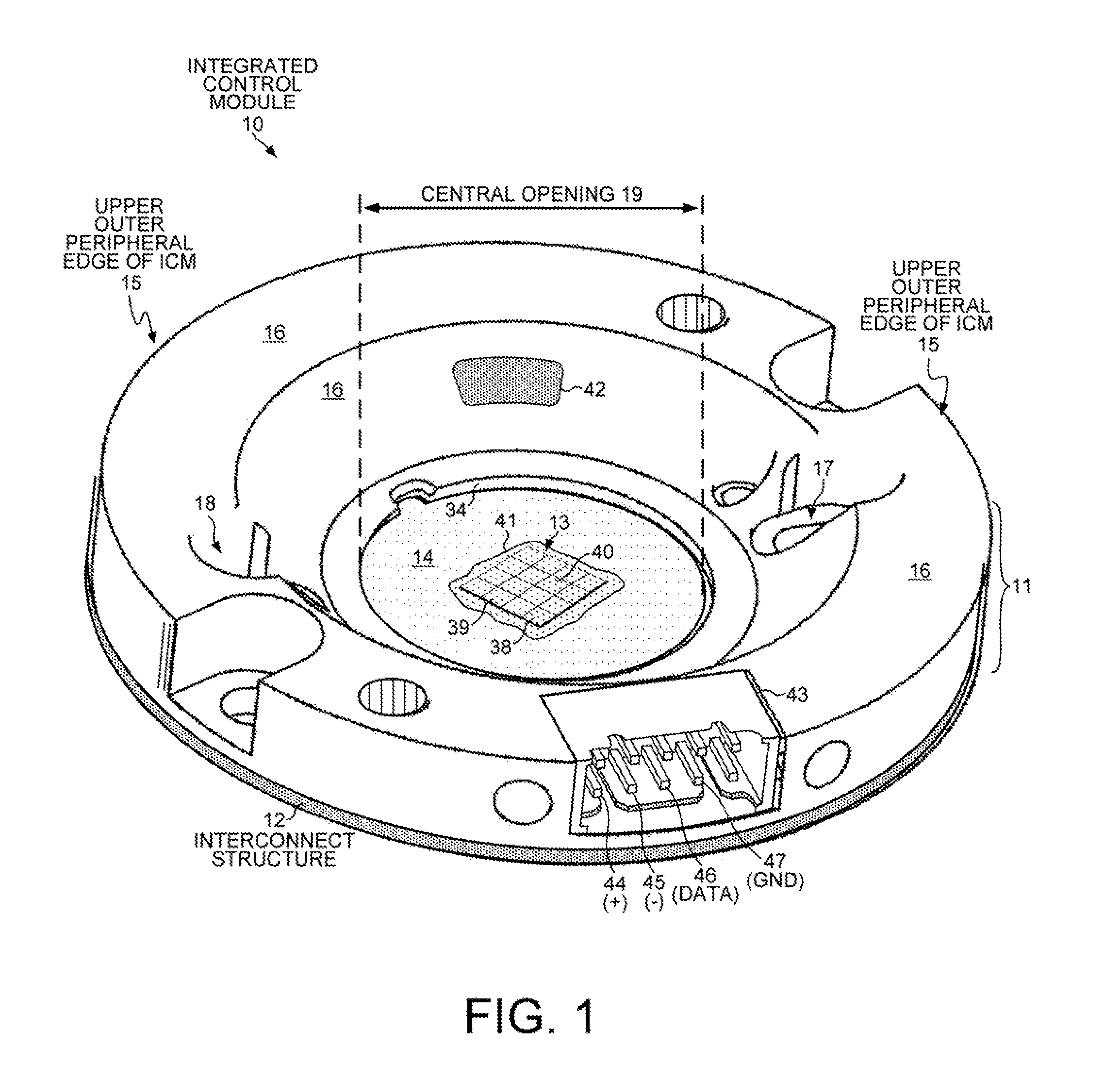
[0026]FIG. 1 is a top perspective view of an integrated control module (“ICM”) 10. ICM 10 is a disk-shaped structure that includes a plastic encapsulant 11 molded over an interconnect structure 12 upon which a monolithic light emitting diode (LED) chip 13 is mounted. The integrated control module 10 allows active electronic components to be embedded in the plastic encapsulant 11 in close proximity to the LED chip 13. The active electronic components monitor, control and provide power to the LED chip 13. Thus, integrated control module 10 is a compact, low-cost, intelligent LED package that can be incorporated into a luminaire using minimal external components.

[0027]ICM 10 has a circular upper outer peripheral edge 15 that circumscribes a toroidal upper surface 16 formed by plastic encapsulant 11. Two holes 17 and 18 are provided...


PUM


Abstract

A lighting device includes a monolithic LED chip flip-chip mounted onto an interconnect structure. The monolithic chip includes LED junctions formed from a single LED junction. An active electronic component is also mounted onto the interconnect structure at a distance from the monolithic chip that is less than five times the maximum dimension of the monolithic chip. The active electronic component controls LED drive currents independently supplied to the LED junctions. Different types of phosphor are disposed laterally above the various LED junctions. A color sensor measures the light emitted from the lighting device when drive currents are supplied to first and second LED junctions. The active electronic component then supplies more drive current to the first LED junction than to the second LED junction in response to the color sensor measuring the light emitted when the prior LED drive currents are supplied to the first and second LED junctions.

Description

TECHNICAL FIELD[0001]The present invention relates generally to packaging of light-emitting diodes.BACKGROUND INFORMATION[0002]A light emitting diode (LED) is a solid state device that converts electrical energy to light. Light is emitted from active layers of semiconductor material sandwiched between oppositely doped layers when a voltage is applied across the doped layers. In order to use an LED chip, the chip is typically enclosed along with other LED chips in a package. In one example, the packaged device is referred to as an LED array. The LED array includes an array of LED chips mounted onto a heat conducting substrate. A layer of silicone in which phosphor particles are embedded is typically disposed over the LED chips. Electrical contact pads are provided for supplying current into the LED array and through the LED chips so that the LED chips can be made to emit light. Light emitted from the LED chips is absorbed by the phosphor particles, and is re-emitted by the phosphor p...

Claims


Application Information

Patent Timeline
Patent Type & Authority Patents(United States)
IPC IPC(8): H05B33/08H01L33/32H01L33/56H01L33/50H01L25/16H01L33/62H01L25/075
CPCH05B33/0869H01L25/0753H01L25/167H01L33/32H01L33/507H01L33/56H01L33/62H01L2924/0002H05B45/22H05B45/46H05B45/395H05B45/375H05B47/14Y02B20/30H01L2924/00H05B45/48H01L33/50H01L33/504
Inventor ODNOBLYUDOV, VLADIMIRDEL, CASTILLO, JESUS
Owner SIGNIFY HLDG BV
Learn More