Intake manifold

a technology of intake manifold and intake manifold, which is applied in the direction of combustion engines, combustion air/fuel air treatment, charge feed systems, etc., can solve the problems of not always the most economical solution to not always the most economical solution to swap out equipment or send otherwise reliable and durable tractor-trailer engines, and not much thought was put into the actual air intake manifold of these engines, so as to improve the overall fuel efficiency and power torque outpu

Inactive Publication Date: 2016-03-01
MKC FLOW
View PDF24 Cites 16 Cited by
  • Summary
  • Abstract
  • Description
  • Claims
  • Application Information

AI Technical Summary

Benefits of technology

[0016]The present invention provides an intake manifold configured to improve the overall fuel efficiency, and power and torque output of an internal combustion in engine. In some embodiments, the intake manifold comprises an asymmetrical plenum having a first end including an inlet, a closed terminal end, a top surface and a bottom surface; a flange; and a plurality of runners extending from the bottom surface of the plenum and terminating at the flange. The plenum defines an interior space in flow communication with the runners. The bottom surface of the plenum is wider than said top surface and, in some embodiments, the cross-section of the plenum has a rounded triangular shape. In some embodiments, the top surface is concave and the bottom surface is convex. The plenum initially widens from the inlet to the first runner and then begins to narrow from the first runner toward the last runner adjacent to the closed terminal end. With this configuration, the intake manifold causes air to exit each of the plurality of runners at substantially the same angle.
[0017]The asymmetrical shape of the runner causes air to initially slow down as it enters the inlet, allowing time for air to enter the first few runners without racing by. Further, the top to bottom taper of the plenum creates a pressure differential across the plenum, with higher pressure at the top and lower pressure toward the entry of the runners which forces air out from the plenum and through to the runners. In some embodiments, the runners are tapered from the plenum toward the flange, are curved, and vary in length to promote air to exit the runners at substantially the same angle. Additionally, an interior aspect of the runners is radiused where the runners meet the bottom surface of the plenum.
[0018]The manifold is configured to bolt-on to a cylinder head at the flange, placing each of the runners in flow communication with a respective conduit of the cylinder head. The manifold is effective to balance the airflow rates across the runners and also provides an optimal angle of air entry into the cylinder head to increase swirl inside the cylinders. The improved airflow balancing and swirl cause a cleaner and more efficient fuel burn which leads to substantial gains in fuel economy, power output and torque.

Problems solved by technology

However, with the onset of ever-increasing fuel costs, efficiency has been brought to the forefront of tractor-trailer technology.
Indeed, newer and more efficient engine designs are always in the pipeline, but it is not always the most economical solution to swap out equipment or send otherwise reliable and durable tractor-trailer engines to end-of-life.
Many solutions for maximizing air flow into the cylinders have been used, such as superchargers and turbochargers (or combinations of the two) but there has not been much thought put into the actual air intake manifolds of the these engines.
Such a design is prone to significant flow and pressure losses and substantial variance in airflow and pressure from one cylinder to the next as inlet air tends to collect at the rear end of the plenum, causing more air to enter the cylinders at the rear leading to a leaner fuel / air ratio as compared to the cylinders toward the front of the plenum, which receive less air and therefore have a richer fuel / air ratio.
An imbalance in airflow rates and in turn cylinder pressure causes an uneven distribution of power across the cylinders leading to decreased overall efficiency, power output, and fuel economy as the “richer” cylinders in effect pull the “leaner” cylinders around the crank shaft.
Several attempts have been made to design intake manifolds that increase power and output, however none are sufficiently engineered to overcome the existing problems with manifolds for large diesel engines.

Method used


Image

  • Intake manifold
  • Intake manifold
  • Intake manifold

Examples


Embodiment Construction

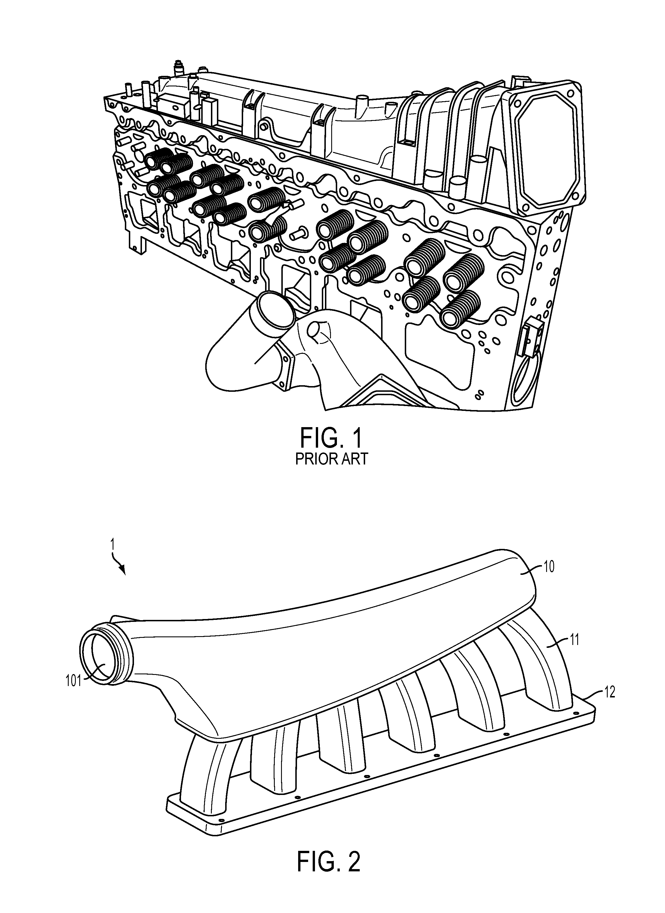
[0037]FIG. 2 is a perspective view of one embodiment of the intake manifold 1 of the present invention. Manifold 1 comprises a plenum 10, a plurality of runners 11, and a flange 12. The runners 11 are disposed longitudinally along the plenum 10 extending from and in flow communication with the plenum 10, terminating at the flange 12. In this exemplary embodiment, the manifold 1 includes six runners 11a, 11b, 11c, 11d, 11e, and 11f corresponding to each cylinder of a six-cylinder diesel engine. The flange 12 provides mounting structure to allow the intake manifold 1 to be secured to a cylinder head of an engine, as will become more apparent throughout this disclosure. In some embodiments, the plenum 10 includes an inlet port 101 at a first end and defines an interior space that is configured to receive air from the inlet port101 and distribute it to the runners 11. The inlet port 101, in some embodiments, receives compressed intake air from an intercooler attached to a turbocharger o...


PUM


Abstract

A bolt-on replacement intake manifold has an asymmetrical plenum with a first end including an inlet, a closed terminal end, a concave top surface and a convex bottom surface; a flange; and a plurality of runners extending from the bottom surface of the plenum and terminating at the flange. The plenum defines an interior space in flow communication with the runners. The bottom surface of the plenum is wider than the top surface. The plenum initially widens from the inlet to the first runner and then begins to narrow from the first runner toward the last runner adjacent to the closed terminal end. The runners are tapered, curved, and vary in length. The intake manifold causes air to exit each of the plurality of runners at substantially the same angle. The manifold balances airflow across each runner and increases swirl inside the cylinders enhancing fuel economy, power output, and torque.

Description

CROSS REFERENCE TO RELATED APPLICATIONS[0001]N / ASTATEMENT REGARDING FEDERALLY SPONSORED RESEARCH OR DEVELOPMENT[0002]N / ABACKGROUND OF THE INVENTION[0003]1. Field of the Invention[0004]The present invention generally relates to components for internal combustion engines and more particularly to an intake manifold for use on high output engines including diesel engines found on semi-trailer trucks.[0005]2. Description of Related Art[0006]It is well established that power and torque output are of utmost importance in the field of semi-trailer and semi-tractor trailer truck engines. Certainly in many instances power and torque are maximized at the expense of fuel economy. However, with the onset of ever-increasing fuel costs, efficiency has been brought to the forefront of tractor-trailer technology. As many tractor-trailers have an average operational life expectancy exceeding ten (10) years, there is a definite need to find ways to increase the efficiency of existing engine designs. I...

Claims


Application Information

Patent Timeline
Patent Type & Authority Patents(United States)
IPC IPC(8): F02M35/104
CPCF02M35/104F02M35/112F02M35/10052F02M35/10078F02M35/10085F02M35/10098Y02T10/146F02M35/1045F02M35/10091Y02T10/12
Inventor WILSON, KEITH
Owner MKC FLOW
Why Eureka
Try Eureka