
Structure for reinforcing seat mounting portion of vehicle body

a technology for vehicle body and seat, which is applied in the direction of vehicle components, superstructure subunits, vehicle arrangements, etc., can solve the problems of cross member deterioration, difficult welding, and deterioration of connection rigidity between side sill members and seat cross members, so as to provide seating stability and protect the occupants.

Active Publication Date: 2016-03-01
HYUNDAI MOTOR CO LTD
View PDF18 Cites 6 Cited by
  • Summary
  • Abstract
  • Description
  • Claims
  • Application Information

AI Technical Summary

Benefits of technology

[0016]The present invention has been made in an effort to provide a structure for reinforcing a seat mounting portion of a vehicle body, which may provide seating stability to an occupant by stably supporting a seat of a vehicle on a vehicle body, and more safely protect the occupant by properly dispersing and absorbing impact energy at the time of a frontal collision or broadside collision accident of the vehicle.
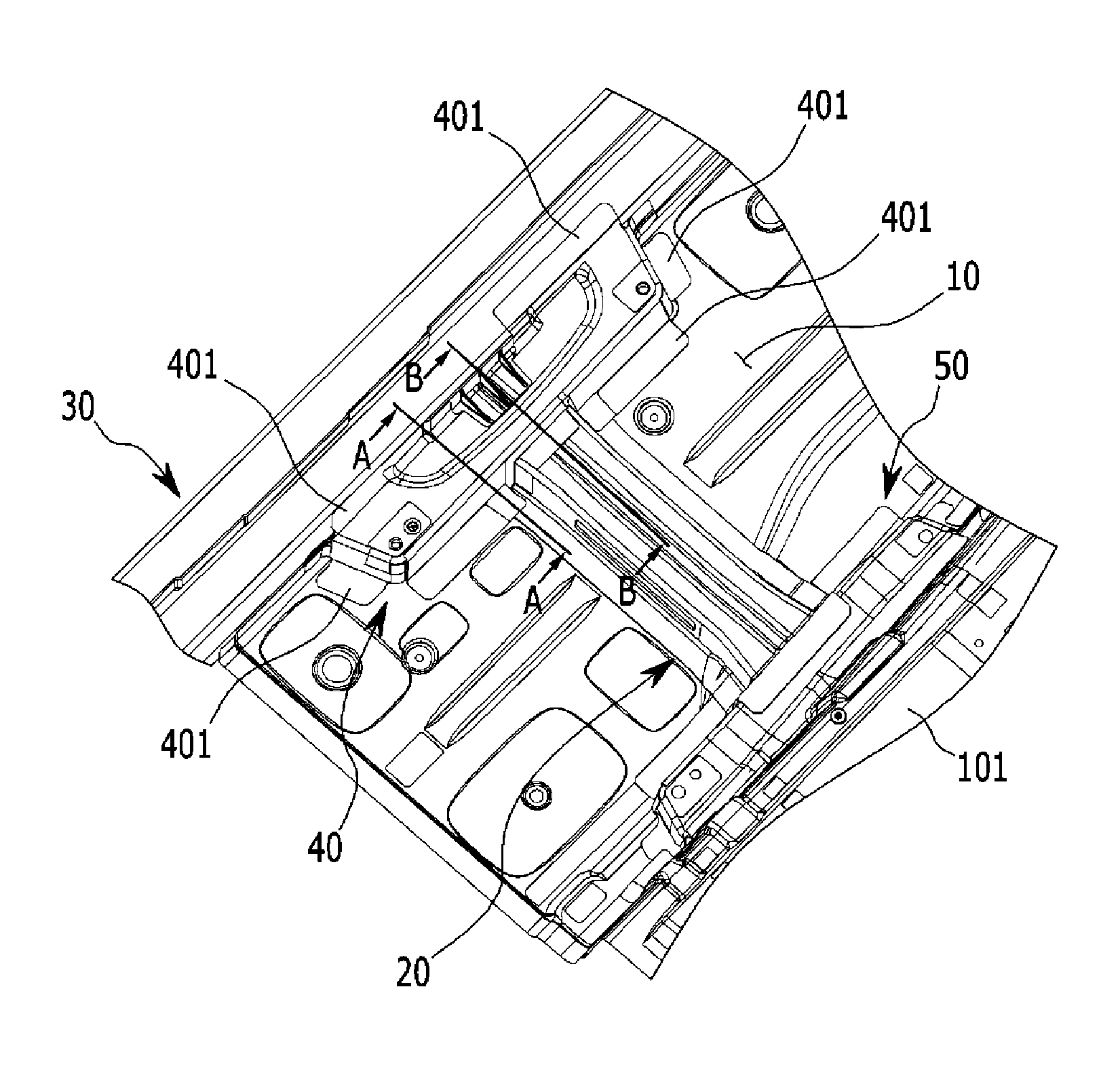
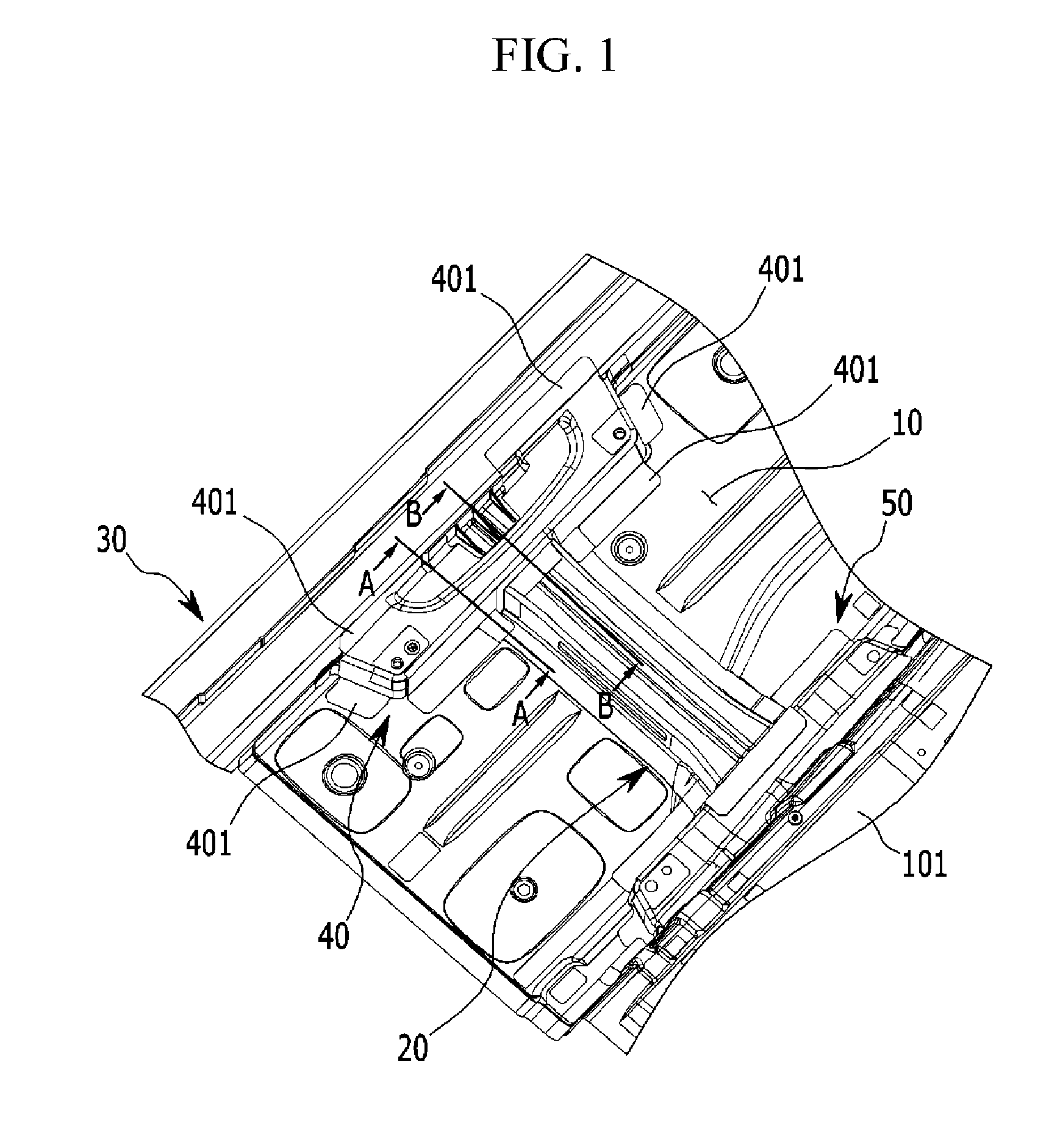
[0017]Various aspects of the present invention provide a structure for reinforcing a seat mounting portion of a vehicle body, including: a floor panel which has a tunnel portion that protrudes in a height direction of a vehicle, and forms a bottom of a vehicle body; side sill members which are formed to be extended in a length direction of the vehicle, and are coupled to the floor panel at both left and right sides in a width direction of the vehicle; a seat inner member which is coupled to the tunnel portion, and on which a seat of the vehicle is mounted; a seat cross member which is disposed to be extended in the width direction of the vehicle, and has an outer tip portion that is coupled to the side sill members, and an inner tip portion that is coupled to the seat inner member; a seat outer member which is superposed on and coupled to the outer tip portion of the seat cross member, and attached to the side sill members and the floor panel, and on which the seat of the vehicle is mounted; and a reinforcing member which is inserted into the seat outer member to reinforce rigidity.
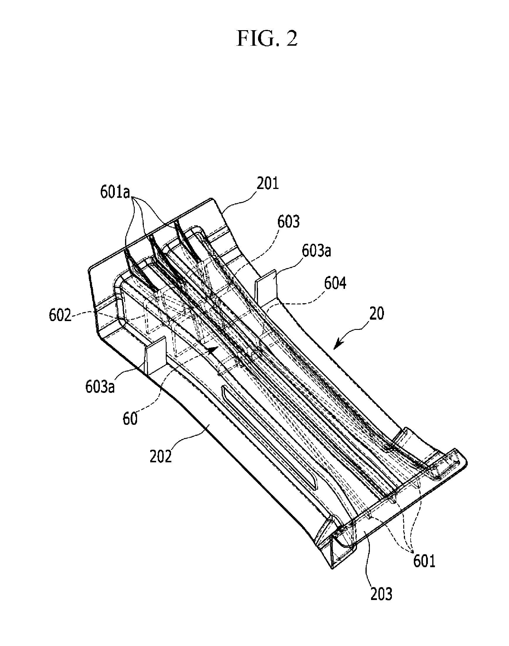
[0026]According to the structure for reinforcing a seat mounting portion of a vehicle body according to various aspects of the present invention, the seat cross member is made by a die casting method such that a degree of design freedom may be improved, and the coupling flanges, which are provided to be coupled to the side sill member, may be formed to have a sufficient area such that connection rigidity between the side sill member and the seat cross member is increased, and support rigidity for the seat of the vehicle is increased.
[0027]In addition, the coupling flanges, which are formed on the outer surface of the seat cross member, increase connection rigidity with the seat outer member so as to suppress moment by which the seat of the vehicle and the seat outer member are rotated toward the front side of the vehicle at the time of a frontal collision accident of the vehicle, thereby stably supporting the seat of the vehicle.
[0028]The side sill member is made by an extrusion method, and the ribs, which are extended upward, downward, leftward, and rightward, are integrally formed in the side sill member, such that multiple cross sections are formed in the side sill member so as to increase structural rigidity of the side sill member, thereby effectively coping with a broadside collision accident of the vehicle, reducing the number of components such as a bulk head in the related art, and reducing the number of manufacturing processes.
[0029]Moreover, the reinforcing members, which are formed to be extended in the length and width directions thereof, are inserted into the seat cross member so as to effectively support the side sill member, prevent rotation of the side sill member, and effectively disperse an impact, which is transmitted through the side sill member, in forward, rearward, leftward, and rightward directions of the vehicle body, at the time of a broadside collision accident of the vehicle, thereby stably protecting the seat of the vehicle and the occupant from the collision accident.

Problems solved by technology

The seat cross member is typically made of a high tensile steel plate in order to cope with a broadside collision of the vehicle such that formability of the seat cross member deteriorates, and a length of a flange, which is adhered to the side sill member, is short such that it is difficult to perform welding, and as a result, there is a problem in that connection rigidity between the side sill member and the seat cross member deteriorates.
In addition, since the bulk head is locally inserted into the side sill member so as to reinforce the side sill member, which does not effectively handle a broadside collision, and as a result, there is a problem in that a connection part between the side sill member and the seat cross member easily buckles at the time of a broadside collision accident of the vehicle.

Method used


Image

  • Structure for reinforcing seat mounting portion of vehicle body
  • Structure for reinforcing seat mounting portion of vehicle body
  • Structure for reinforcing seat mounting portion of vehicle body

Examples


Embodiment Construction

[0036]Reference will now be made in detail to various embodiments of the present invention(s), examples of which are illustrated in the accompanying drawings and described below. While the invention(s) will be described in conjunction with exemplary embodiments, it will be understood that present description is not intended to limit the invention(s) to those exemplary embodiments. On the contrary, the invention(s) is / are intended to cover not only the exemplary embodiments, but also various alternatives, modifications, equivalents and other embodiments, which may be included within the spirit and scope of the invention as defined by the appended claims.

[0037]Referring to FIG. 1, a structure for reinforcing a seat mounting portion of a vehicle body according to various embodiments of the present invention may include a seat cross member 20 that is disposed on a floor panel 10 in a width direction of a vehicle. The seat cross member 20 may have an approximate “”-shaped cross section t...


PUM


Abstract

A structure for reinforcing a seat mounting portion of a vehicle body may include a floor panel having a tunnel portion that protrudes in a height direction of a vehicle, side sill members extended in a length direction of the vehicle and coupled to the floor panel at both left and right sides in a width direction of the vehicle, a seat inner member coupled to the tunnel portion, a seat cross member extended in the width direction of the vehicle and having an outer tip portion coupled to the side sill members and an inner tip portion coupled to the seat inner member, a seat outer member coupled to the outer tip portion of the seat cross member and attached to the side sill members and the floor panel, and a reinforcing member inserted into the seat outer member to reinforce rigidity.

Description

CROSS-REFERENCE TO RELATED APPLICATION[0001]The present application claims priority of Korean Patent Application Number 10-2013-0158644 filed on Dec. 18, 2013, the entire contents of which application are incorporated herein for all purposes by this reference.BACKGROUND OF INVENTION[0002]1. Field of Invention[0003]The present invention relates to a structure for reinforcing a seat mounting portion of a vehicle body, and more particularly, to a structure for reinforcing a seat mounting portion of a vehicle body, which may stably protect an occupant by stably supporting a seat on a vehicle body at the time of a frontal collision or broadside collision accident of the vehicle.[0004]2. Description of Related Art[0005]A seat of a vehicle in the related art is mounted and supported on a floor panel, which constitutes a bottom of the interior of the vehicle, in an internal space of the interior of the vehicle which is formed in a vehicle body.[0006]The seat of the vehicle needs to be stabl...

Claims


Application Information

Patent Timeline
Patent Type & Authority Patents(United States)
IPC IPC(8): B62D25/00B62D25/20B60N2/005
CPCB60N2/005B62D25/2036B62D25/2009
Inventor HAN, YOONKYOUNGCHA, MUN, SOO
Owner HYUNDAI MOTOR CO LTD
Learn More