
Extended hub for a safety pen needle

a safety pen and hub technology, applied in the field of injection devices, can solve the problems of less sensible pressure on the patient's tissue, and achieve the effects of facilitating appropriate insertion depth, limiting the injection depth, and easy change of design

Active Publication Date: 2016-03-01
EMBECTA CORP
View PDF17 Cites 8 Cited by
  • Summary
  • Abstract
  • Description
  • Claims
  • Application Information

AI Technical Summary

Benefits of technology

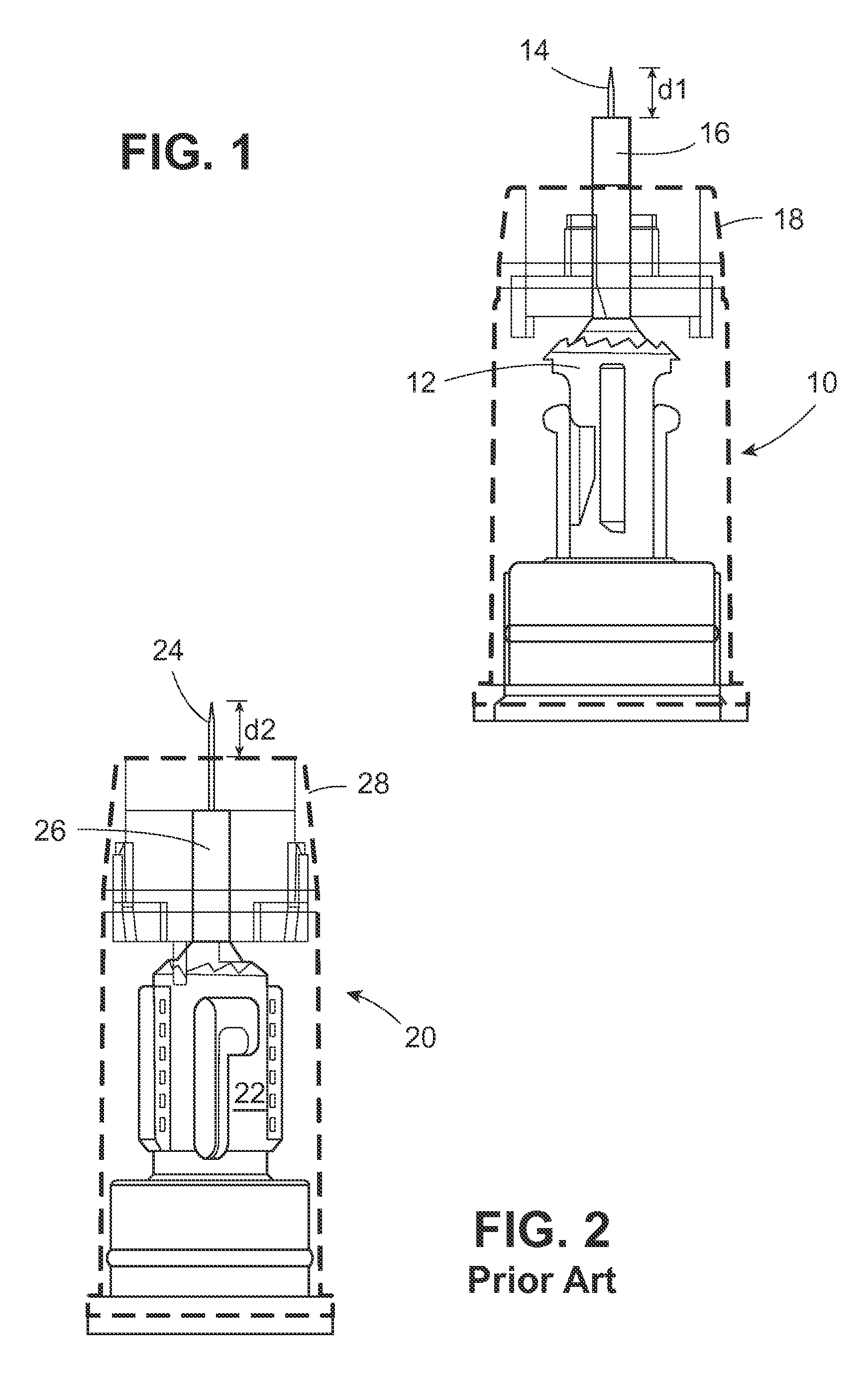
[0007]Thus, in the embodiments described above, the effective penetration depth of the needle cannula is from the distal tip of the needle to the distal end of the hub. When the patient or health care professional administers an injection, the injection force is concentrated on the relatively small area of the distal end of the hub rather than being distributed to the ring formed by the outer sleeve. The device facilitates appropriate insertion depth compared to prior art safety shield devices because the concentration of force on the distal end of the hub prevents the spring-biased inner shield from moving past that point on the hub, whereas, distributing force on the outer sleeve, as in the prior art, may permit the inner shield to protrude distally beyond the outer sleeve, potentially limiting the injection depth.
[0008]Where the passive safety shield is urged in a distal direction to cover the needle cannula after administering an injection, the passive shield need only move from the distal end of the hub to a position covering the needle. Because less spring force is required to power the passive shield this short distance, less sensible pressure is exerted against the patient's tissue.
[0009]Except for the hub extension, the parts of the shield assembly are similar to, and in some embodiments, identical to, prior art shield systems. Consequently, designs are changed over easily, and interoperability of many parts is ensured.

Problems solved by technology

The device facilitates appropriate insertion depth compared to prior art safety shield devices because the concentration of force on the distal end of the hub prevents the spring-biased inner shield from moving past that point on the hub, whereas, distributing force on the outer sleeve, as in the prior art, may permit the inner shield to protrude distally beyond the outer sleeve, potentially limiting the injection depth.
Because less spring force is required to power the passive shield this short distance, less sensible pressure is exerted against the patient's tissue.

Method used


Image

  • Extended hub for a safety pen needle
  • Extended hub for a safety pen needle
  • Extended hub for a safety pen needle

Examples


Embodiment Construction

[0019]As used herein, the “distal” direction is in the direction of the injection site, and the “proximal direction” is the opposite direction. The “axial” direction is along the longitudinal axis of the injection device. The needle cannula is generally arranged axially in the device. “Radially” is a direction perpendicular to the axial direction. Thus, “radially inward” generally means closer to the needle. “Integral” means one-piece in the state normally encountered by the user—not intended to be taken apart easily. A “passive” shield is a shield on an injection device which is urged automatically into a position covering the needle cannula after an injection is administered without requiring manipulation by the user or health care professional.

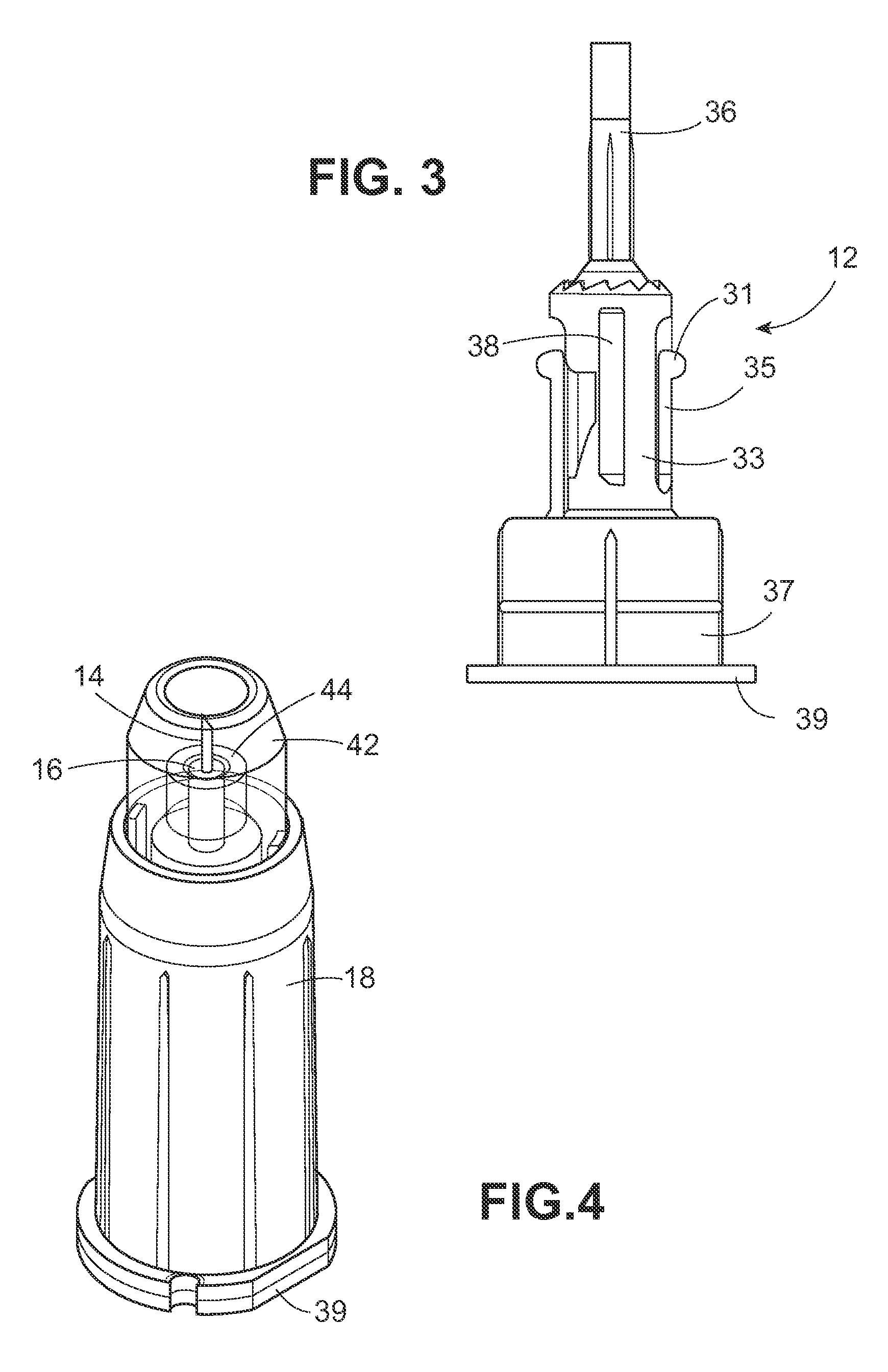
[0020]FIG. 1 shows a partial pen needle assembly 10 including the extended hub post 16 on hub 12 positioned distally of the outer sleeve 18 which is shown in outline. The inner and outer sleeves are removed from FIG. 1 to more clearly delin...


PUM


Abstract

A shielded pen needle assembly is provided in which the hub extends distally beyond an outer sleeve of the assembly.

Description

BACKGROUND OF THE INVENTION[0001]1. Field of the Invention[0002]The invention is in the field of injection devices having an automated shield for covering the needle after an injection, and specifically the invention is directed to a safety pen needle having an extended hub.[0003]2. Description of the Related Art[0004]The prior art teaches various safety shield systems adapted for use with a medication pen. Examples of passive shielding systems include those described in U.S. Patent Application Publication Nos. 2011 / 0288491 and 2011 / 0257603, which are incorporated by reference. Typically, the penetration depth of the needle in a shielded medication pen is defined by the distance from the needle tip to the distal end of an outer sleeve, which forms an outer periphery of the device. The inventor has explored a pen needle shield system in which the injection depth of the needle is defined without reference to the position of the outer sleeve.SUMMARY OF THE INVENTION[0005]Thus, in one a...

Claims


Application Information

Patent Timeline
Patent Type & Authority Patents(United States)
IPC IPC(8): A61M5/46A61M5/32A61M5/34
CPCA61M5/46A61M5/3202A61M5/326A61M5/3213A61M5/3257A61M5/3243A61M5/3271A61M5/347A61M2005/3247A61M2005/3254A61M2005/3263A61M2005/3267
Inventor HERR, JOSHUA
Owner EMBECTA CORP
Learn More