
Image generator and projector

a technology of image sensor and generator, which is applied in the field of scene generation system for testing image sensors, can solve the problems of limited collimation output of generator and projector, high cost and time consumption, and limit the testing to a single sensor device or camera at any one time, and achieve good resolution

Active Publication Date: 2016-02-23
HARRIS CORP
View PDF5 Cites 3 Cited by
  • Summary
  • Abstract
  • Description
  • Claims
  • Application Information

AI Technical Summary

Benefits of technology

The present invention is a housing with a spherical mirror, an aperture stop, and a focal area. The focal area is located between the aperture stop and the spherical mirror. The housing also includes a light to illuminate the focal area. When the light shines on the focal area, the spherical mirror reflects the area towards the aperture stop. The focal area has a plate with small holes that allow the light to reflect onto the aperture stop. These small holes depict an object, and when the light passes through the holes, the object is projected onto the aperture stop. The technical effect of this design is that it provides a way to capture and display objects in a unique and interesting way.

Problems solved by technology

This is an essential part of any new missile development program, although it is very expensive and time consuming.
These generators and projectors, however, are limited for producing collimated, but narrow fields-of-view that provide only partial field coverage or are limited in resolution or available aperture, precluding the simultaneous testing of systems comprising a multiplicity of cameras.
This effectively limits testing to a single sensor device, or camera at any one time.

Method used


Image

  • Image generator and projector
  • Image generator and projector
  • Image generator and projector

Examples


Embodiment Construction

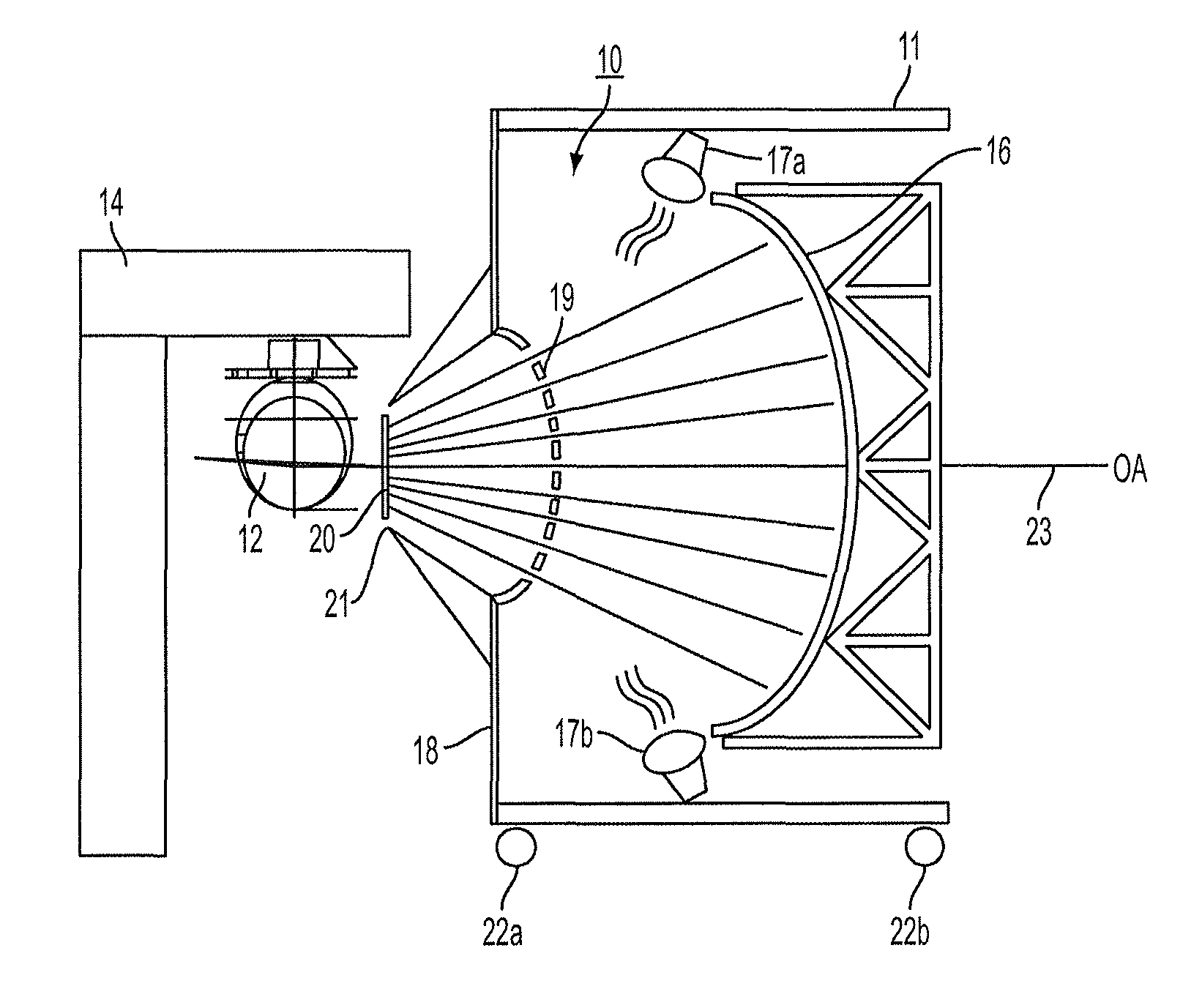
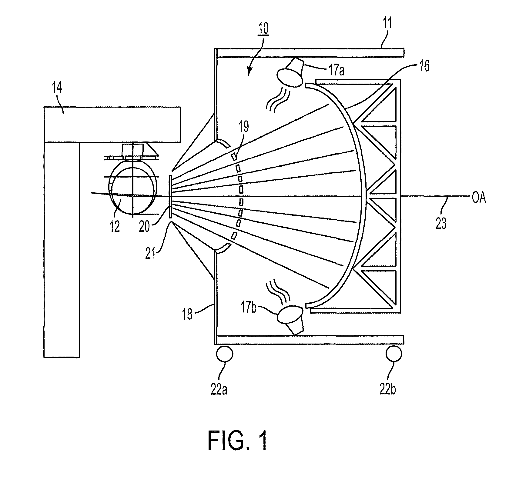
[0046]As will now be explained, with reference to the figures, the present invention provides an image generator and projector for end-to-end testing of multiple image sensors that are simultaneously capable of viewing a very wide field-of-view (FOV). The FOV may for example, accommodate fully 76° visible and / or IR imaging of a target of interest. The image projector of the present invention is capable of generating and projecting a collimated test target toward the multiple image sensors for simulating a very wide scene for viewing by the image sensors, covering as much as a 76° FOV and beyond.

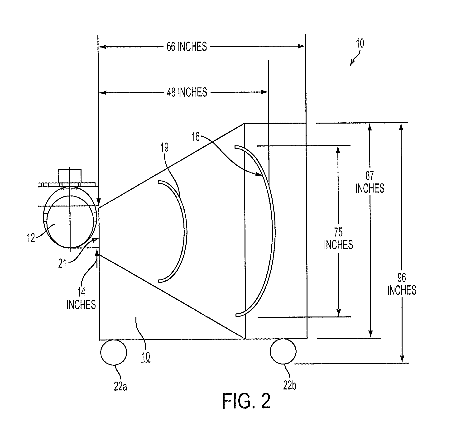
[0047]Referring first to FIGS. 1 and 2, there is shown an image generator and projector system, generally designated as 10. As shown, system 10 includes a large housing 11, which may be 96 inches in height, 96 inches in width, and 66 inches in depth (as an example). The housing 11 includes a spherical mirror 16, a target object 19, and an opening for providing an aperture stop, the latter des...


PUM


Abstract

A generator and projector system for providing a test target for testing sensing apparatus includes an aperture stop located adjacent to the sensing apparatus. Also included are a spherical mirror having a concave side facing the aperture stop and an object disposed between the spherical mirror and the aperture stop. The object includes various test targets for testing the sensing apparatus. A longitudinal optical axis passes through the aperture stop, the spherical mirror and the object. Illumination of the object generates the test target, which is then reflected from the spherical mirror toward the aperture stop, for testing the sensing apparatus.

Description

FIELD OF THE INVENTION[0001]The present invention relates, in general, to scene generation systems for testing image sensors, such as infrared (IR) sensors and visible imaging sensors. More specifically, the present invention relates to an image scene generator and projector for end-to-end testing of multiple image sensors that are capable of viewing a very wide field-of-view (FOV).BACKGROUND OF THE INVENTION[0002]It is desirable to generate a synthetic scene for testing and calibrating various image sensors, such as visible, ultraviolet and infrared (IR) imaging devices. There has been progress in developing scene projectors for use in Hardware-in-the-Loop (HWIL) Simulations that are capable of end-to-end testing and calibration of imaging devices, or sensors.[0003]For example, it is common to incorporate seekers into missiles, for guiding the missile onto a target. When a new missile is developed it must be tested to ensure that the design is robust and that it behaves the way it ...

Claims


Application Information

Patent Timeline
Patent Type & Authority Patents(United States)
IPC IPC(8): G03B21/00
CPCG03B21/00G03B37/04G03B43/00
Inventor DEY, THOMAS, WILLIAM
Owner HARRIS CORP
Learn More