
Clamp device

a technology of clamping device and clamping body, which is applied in the direction of positioning apparatus, metal-working machine components, manufacturing tools, etc., can solve the problems of deteriorating machining accuracy, workpiece clamping, and irregular machined plane, so as to reduce the diameter, reliably lock the cylindrical clamp body, and reduce the diameter

Active Publication Date: 2016-01-26
PASCAL ENG
View PDF17 Cites 5 Cited by
  • Summary
  • Abstract
  • Description
  • Claims
  • Application Information

AI Technical Summary

Benefits of technology

The present invention is a clamp device that can change its height position to match the surface of a workpiece, and securely hold the clamp body in place. The cylindrical clamp body can be raised, made contact with the workpiece, and then lowered to release it. This allows for easy positioning and stable support during machining, suppressing deformation and improving accuracy. The clamp can be locked in place using a lock mechanism, and the grip member can be expanded to bite into the workpiece, ensuring planarity and stability during machining. The clamp can also be locked by elastically deforming the cylindrical member or the annular member, providing reliable support and stability during machining.

Problems solved by technology

However, if the plurality of surfaces to be supported are at different height positions, or if, although the plurality of surfaces to be supported are at the same height position, there is some deviation between the surfaces to be supported, then there is the problem that the machined plane may be somewhat irregular after machining.
In concrete terms if, after the external peripheral portion of the workpiece has been clamped at three locations, it is then clamped at one more location, then there is a fear that the workpiece may be clamped in a state in which it is not reliably contacted against all the seating surfaces of the clamp body, or that the workpiece may be clamped in a state in which it is slightly distorted, both of which would be undesirable.
If, due to this, the workpiece is supplied to machining in an imperfectly clamped state, then there is the problem that the machining accuracy may be deteriorated due to elastic deformation of the workpiece or due to chattering vibration.

Method used


Image

  • Clamp device
  • Clamp device
  • Clamp device

Examples


embodiment 1

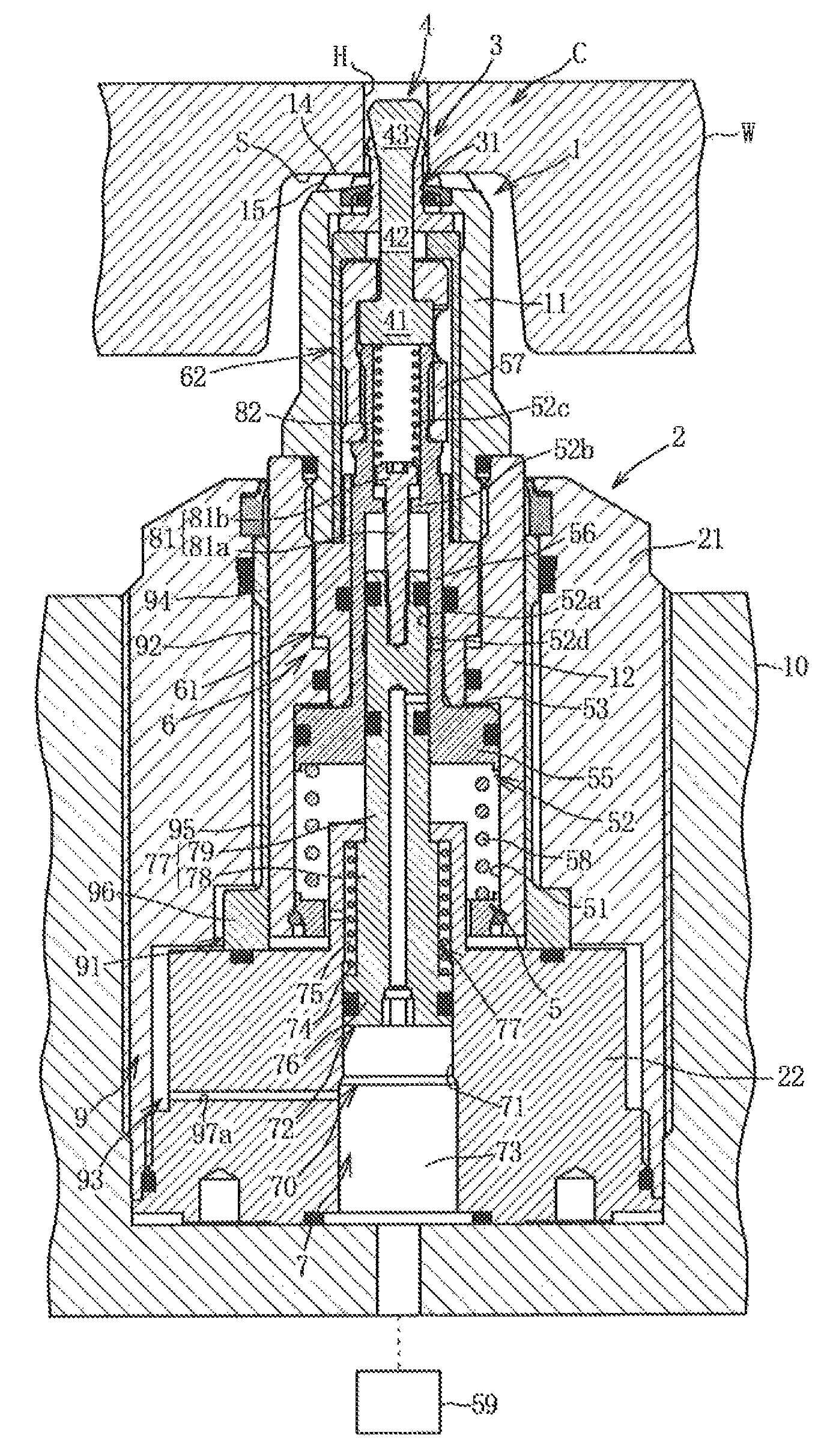
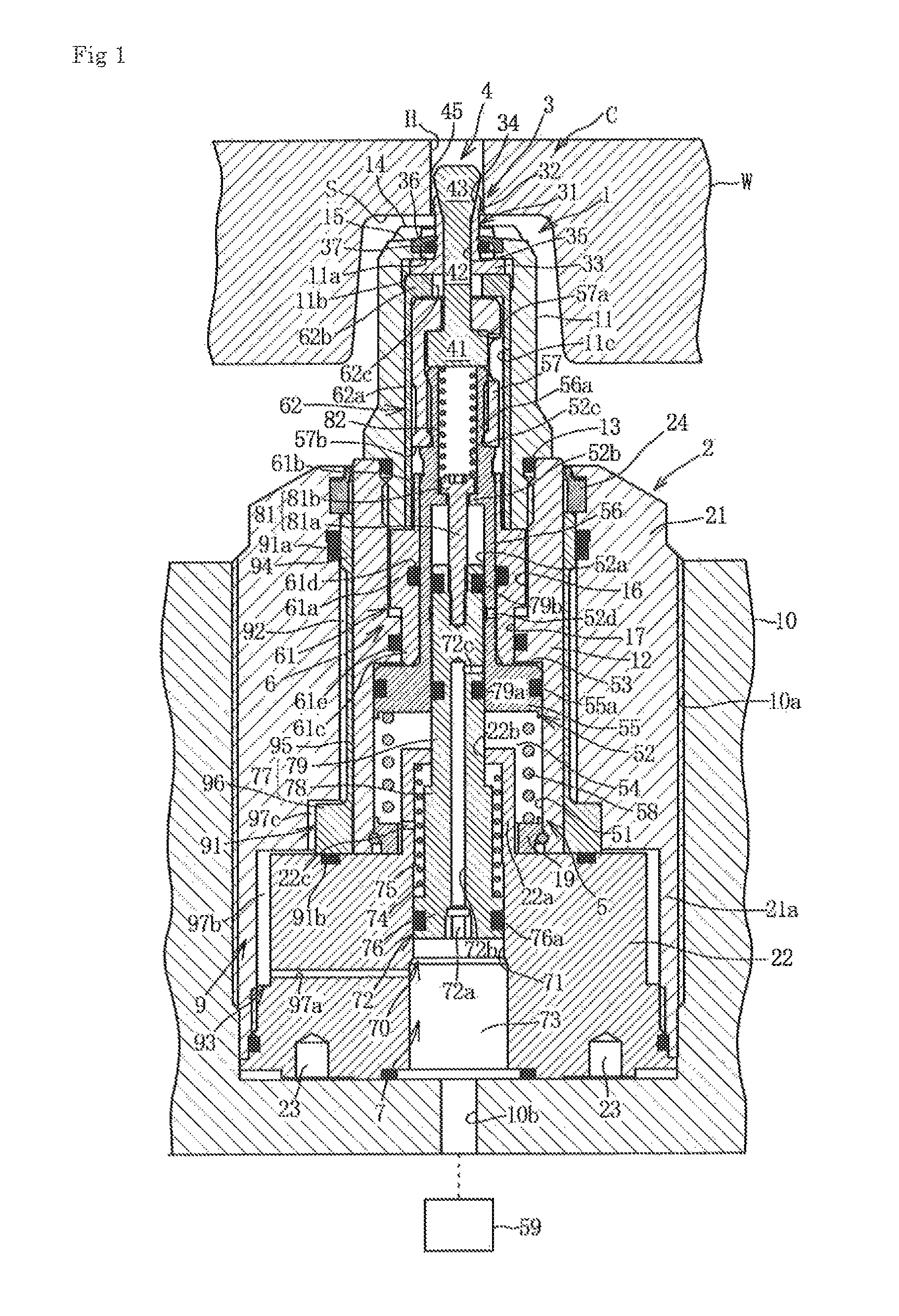
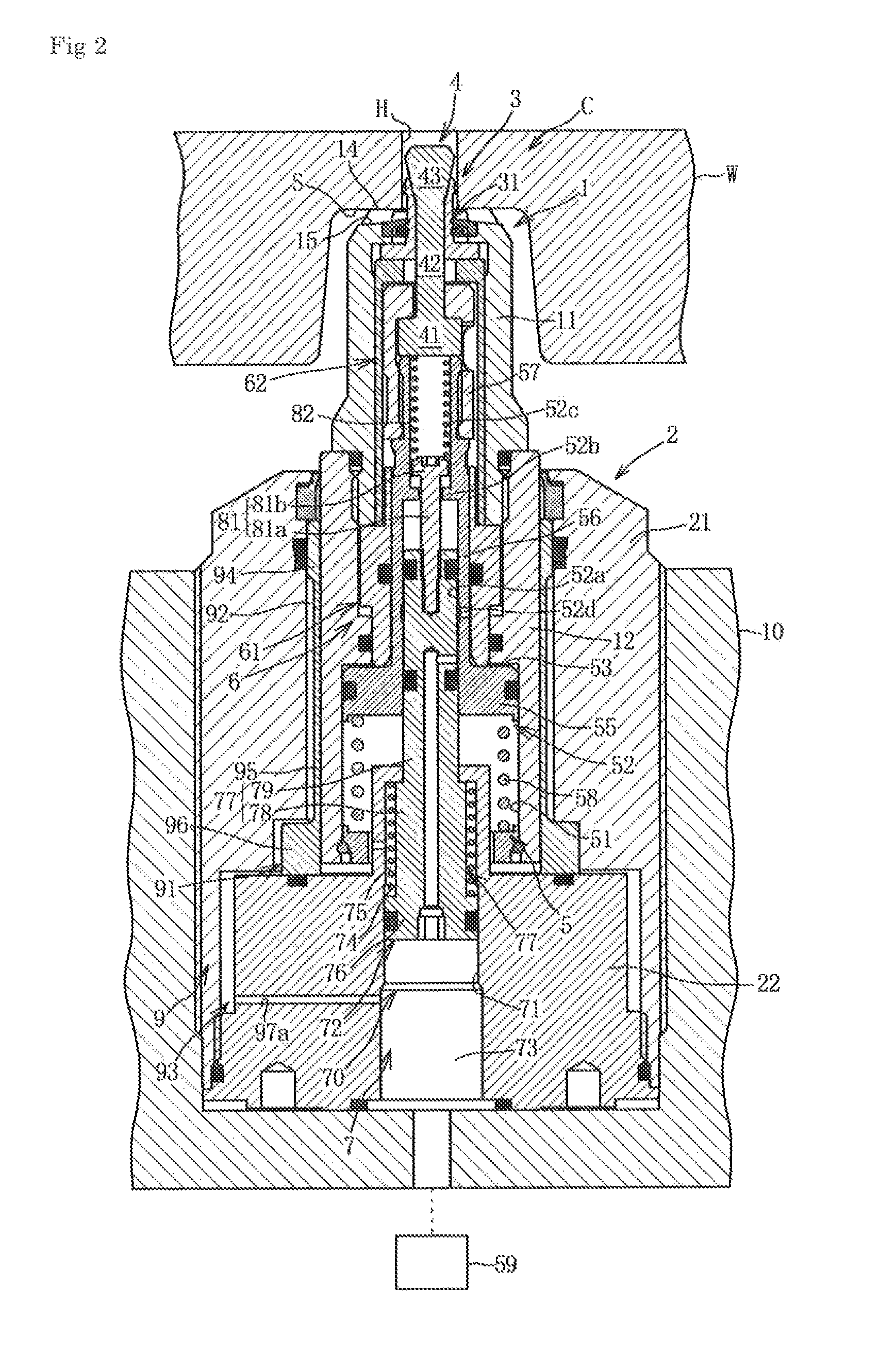
[0033]As shown in FIGS. 1 through 3, this clamp device C is one in which, after a surface to be supported S of a workpiece W (i.e. an article) to be supplied to machine processing has been supported from below, and a cylindrical clamp body 1 has been fixated, the inner circumferential surface of an aperture H in the workpiece W is put into a state of being gripped by a grip member 3. This clamp device C comprises a cylindrical clamp body 1, a case member 2 that supports the cylindrical clamp body 1 so that it can move forwards and backwards, the grip member 3, a clamp rod 4, a forwards / backwards driving mechanism 5 that can drive the clamp rod 4 forwards and backwards, a support mechanism 6 that supports the clamp rod 4, an elevating / lowering driving mechanism 7 that can drive the cylindrical clamp body 1 to be raised and lowered (to be moved up and down), and a lock mechanism 9 that can fixate the outer circumferential surface of the cylindrical clamp body 1.

[0034]First, the cylind...

embodiment 2

[0078]While, in this embodiment, an example will be explained in which the clamp device C described above is partially altered, similar reference numerals will be appended to structural elements thereof that are similar to elements of the first embodiment, and explanation of those elements will be omitted, with only the structural elements that are different being explained. It should be understood that the clamp device CA of this second embodiment is one in which the construction of the lock mechanism 9 of the first embodiment described above is altered.

[0079]As shown in FIGS. 4 through 6, this clamp device CA comprises a cylindrical clamp body 1, a case member 2A that supports the cylindrical clamp body 1 so that it can move forwards and backwards, the grip member 3, a clamp rod 4, a forwards / backwards driving mechanism 5, a support mechanism 6 that supports the clamp rod 4, an elevating / lowering driving mechanism 7, and a lock mechanism 9A, but, apart from the lock mechanism 9A, ...


PUM


Abstract

A grip member is inserted into an insertion hole of a cylindrical clamp body and is capable of extending outwards to grip the inner circumferential surface of an aperture of an article. A clamp rod is engaged with the grip member; a driving mechanism capable of driving the clamp rod forwards and backwards; a seating surface formed at the top end of the cylindrical clamp body; a case member supporting the cylindrical clamp body movably forwards and backwards; a driving mechanism capable of raising an lowering the cylindrical clamp body; and a lock mechanism having a cylindrical member into which the cylindrical clamp body is inserted so as to slide freely and capable of locking the outer circumferential surface of the cylindrical clamp body by elastically deforming the cylindrical member so as to reduce its diameter.

Description

TECHNICAL FIELD[0001]The present invention relates to a clamp device that grips the inner circumferential surface of an aperture in an article such as a workpiece or the like by expanding the diameter of a grip member that is inserted into the aperture, and in particular relates to a clamp device that is endowed with a function of changing the height position of a clamp body in correspondence to the height position of a surface to be supported of the article, and that thereafter is capable of fixating the clamp body.BACKGROUND OF THE INVENTION[0002]From the prior art, clamp devices of various types such as hole clamps or expansion clamps and so on have been put into practical use. With these clamp devices, the inner circumferential surface of an aperture in an article such as a workpiece is gripped by expanding, with a clamp rod, the diameter of a grip claw portion of a grip member that has been inserted into the aperture as described above, and then the article is pulled towards th...

Claims


Application Information

Patent Timeline
Patent Type & Authority Patents(United States)
IPC IPC(8): B23Q3/08B23Q1/00
CPCB23Q3/082B23Q1/009B23Q3/06B23Q3/18
Inventor KAWAKAMI, TAKAYUKI
Owner PASCAL ENG
Learn More