
Zoom lens and image pickup apparatus having the same

a pickup apparatus and zoom lens technology, applied in the field of zoom lens, can solve the problems of large amount of shading generated, difficult to place the ranging member used for the phase difference af without increasing the thickness of the camera, and difficult to perform the phase difference af in a wide shooting range over the entirety of the object distance from an infinite object to a macro range, etc., to achieve high optical performance, easy to perform focusing operation, and high speed

Active Publication Date: 2015-12-29
CANON KK
View PDF30 Cites 0 Cited by
  • Summary
  • Abstract
  • Description
  • Claims
  • Application Information

AI Technical Summary

Benefits of technology

[0015]The present invention provides a zoom lens with a wide angle of view having a high optical performance over an entire zoom range which easily performs a focusing operation at high speed.

Problems solved by technology

However, since the mirrorless camera does not have the mirror box, there is little space for placing the ranging mirror used for the phase difference AF, and therefore it is very difficult to place the ranging member used for the phase difference AF without increasing the thickness of the camera.
When the phase difference AF of a twin-lens external method is adopted, it is difficult to perform the phase difference AF in a wide shooting range over the entirety of an object distance from an infinite object to a macro range as a zoom range from a wide angle end to a telephoto end.
Therefore, an incident angle of a ray onto the image pickup element is increased, and therefore a large amount of shading is generated when using an electronic image pickup element.
For example, if the lens configuration of the first lens unit or the third lens unit, the refractive power of the second, third, or fourth lens unit, or the like is not appropriately set, it is difficult to have a high optical performance over the entirety of the zoom range at the wide angle of view while achieving the reduction in size of the total system so as to perform the high-speed focusing operation.
In an interchangeable zoom lens used for the camera system with interchangeable lenses, when a lens unit disposed closest to the image side is moved during the focusing operation, an interference of an actuator that moves the lens unit disposed closest to the image side with a mount member is a problem.

Method used


Image

  • Zoom lens and image pickup apparatus having the same
  • Zoom lens and image pickup apparatus having the same
  • Zoom lens and image pickup apparatus having the same

Examples


embodiment 1

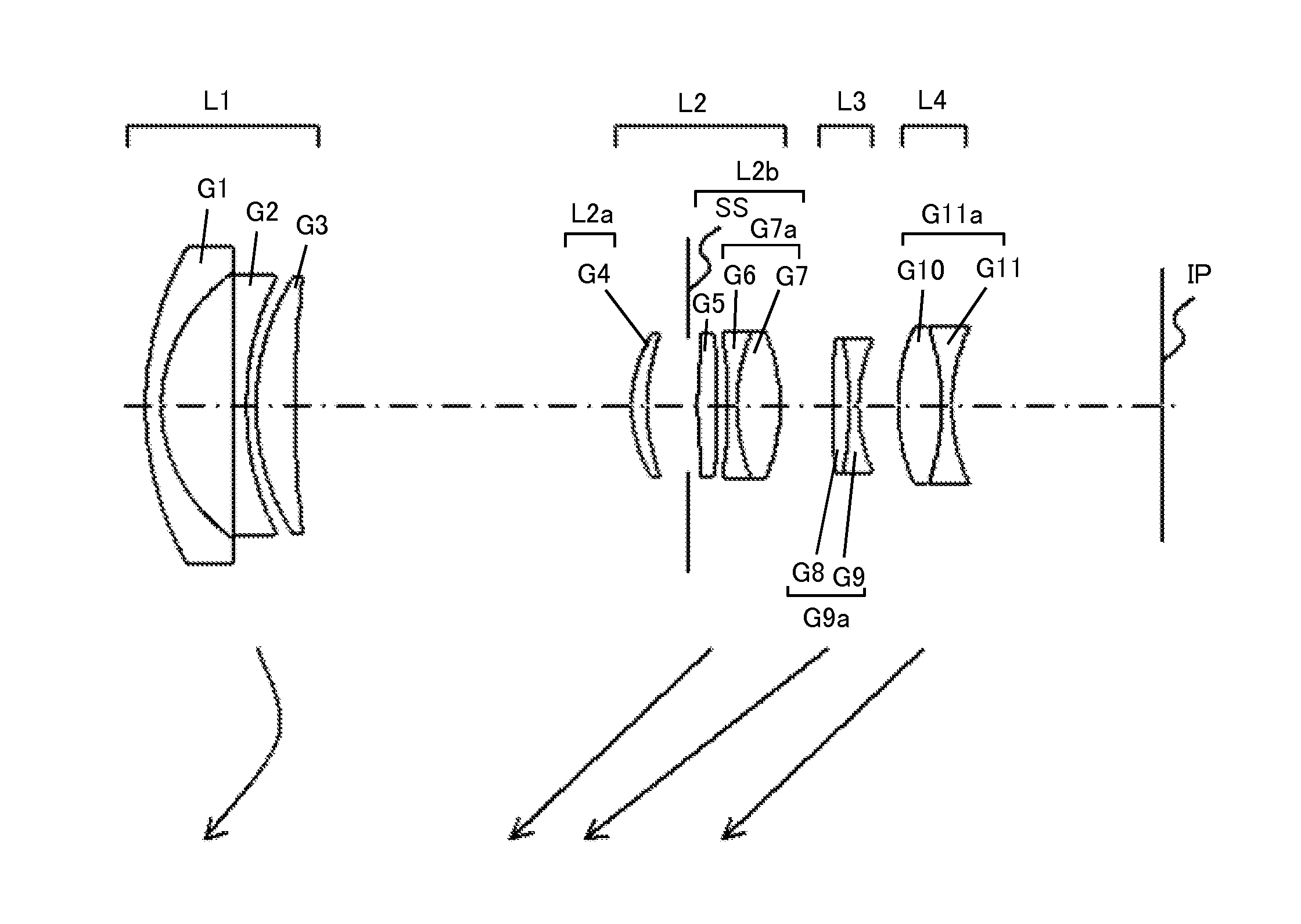
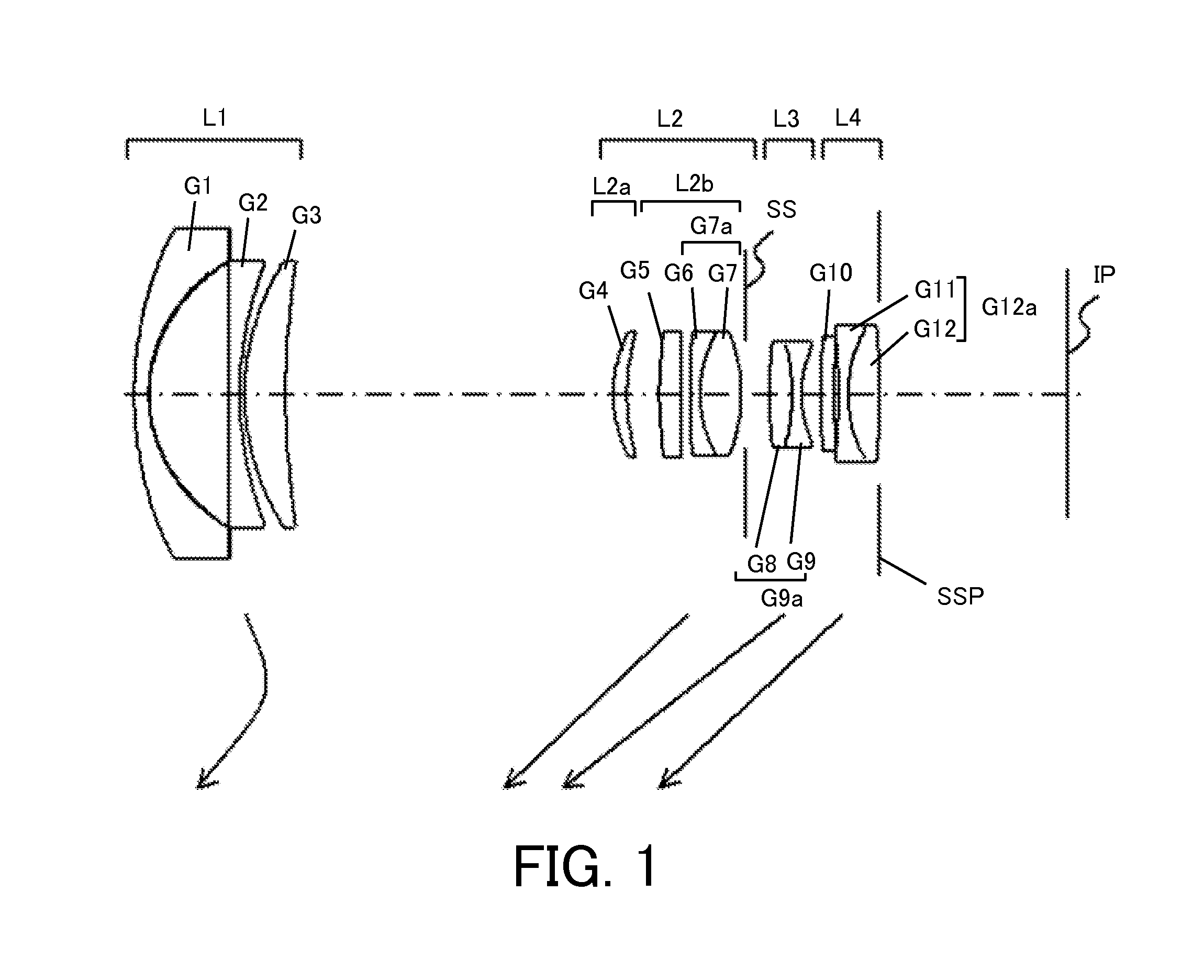
[0056]Embodiment 1 described with reference to FIG. 1 is directed to a four-unit zoom lens that has, in order from the object side to the image side, the first lens unit L1 to the fourth lens unit L4 having negative, positive, negative, and positive refractive powers, respectively.

[0057]When the zooming operation from the wide angle end to the telephoto end is performed, the first lens unit L1 is moved along a locus convex towards the image side as indicated by an arrow so as to compensate the variation of the image plane caused by the magnification varying operation. The second lens unit L2, the third lens unit L3, and the fourth lens unit L4 are lens units for the magnification varying operation, each of which is moved to the object side. The aperture stop SS is disposed at the image side of the second lens unit L2, which is moved integrally with the second lens unit L2. The second lens unit L2 and the fourth lens unit L4 are integrally moved along the same locus. Each lens unit i...

embodiment 2

[0061]A zoom lens of Embodiment 2 described with reference to in FIG. 3 has the same zoom type and focus method as those of Embodiment 1. On the other hand, the refractive power arrangement and the lens configuration in the lens units are different from those of Embodiment 1. In Embodiment 2, the aperture stop SS is disposed in the second lens unit L2, which is moved integrally with the second lens unit L2 during the zooming operation. Each lens unit is, in order from the object side to the image side, configured as follows.

[0062]The first lens unit L1 is configured by a negative lens G1 having a convex meniscus surface at the object side, a negative lens G2 having a biconcave shape, and a positive lens G3 having a convex meniscus surface at the object side. The second lens unit L2 is configured by a positive lens G4 having a convex meniscus surface at the object side, an aperture stop SS, a positive lens G5 having both aspherical surfaces and having a biconvex shape, and a cemented...

embodiment 3

[0063]A zoom lens of Embodiment 3 described with reference to in FIG. 5 has the same zoom type and focus method as those of Embodiment 1. On the other hand, the refractive power arrangement and the lens configuration in the lens units are different from those of Embodiment 1. Each lens unit is, in order from the object side to the image side, configured as follows.

[0064]The first lens unit L1 is configured by a negative lens G1 having a convex meniscus surface at the object side, a negative lens G2 having a biconcave shape, and a positive lens G3 having a convex meniscus surface at the object side. The second lens unit L2 is configured by a positive lens G4 having an aspherical and convex meniscus surface at the object side and a cemented lens G6a formed by cementing a negative lens G5 having a convex and negative meniscus surface at the object side and a positive lens G6 having a biconvex shape.

[0065]The third lens unit L3 is configured by a negative lens G7 having an aspherical su...


PUM


Abstract

A zoom lens includes a first lens unit having a negative refractive power, a second lens unit having a positive refractive power, a third lens unit having a negative refractive power, and a fourth lens unit having a positive refractive power, disposed in order from an object side to an image side, and an aperture stop between a lens surface closest to the object side of the second lens unit and a lens surface closest to the object side of the third lens unit, the third lens unit is moved to the image side during a focusing operation from an infinite object to a short distance object, the first lens unit is configured by at most two negative lenses and one positive lens, the third lens unit is configured by a single lens or a cemented lens, and an appropriate conditional expression are met.

Description

BACKGROUND OF THE INVENTION[0001]1. Field of the Invention[0002]The present invention relates to a zoom lens, which is suitably used for an image pickup apparatus using a solid-state image pickup element, such as a digital still camera, a video camera, a television camera, or a surveillance camera.[0003]2. Description of the Related Art[0004]In a camera with interchangeable lenses, a camera having a function of displaying image data, generated by an image pickup lens and an image pickup element, on a display element (a live view function) in accordance with computerization of the image pickup element is known. In these cameras with the interchangeable lenses, a mirrorless camera that removes an optical finder using a quick return mirror, a pentaprism capable, and the like, and that is capable of confirming a shooting image using the live view function described above is known. Since this mirrorless camera removes the quick return mirror, the thickness of the camera is easily reduced...

Claims


Application Information

Patent Timeline
Patent Type & Authority Patents(United States)
IPC IPC(8): G02B27/64G02B15/22G02B15/14G02B15/24G02B15/177
CPCG02B15/14G02B27/646G02B15/22G02B15/177G02B15/144511
Inventor TASHIRO, YOSHIHISAHAGIWARA, YASUAKI
Owner CANON KK
Learn More