
Airbag inflation systems and methods

a technology of airbags and inflation systems, applied in the direction of pedestrian/occupant safety arrangements, separation processes, vehicular safety arrangements, etc., can solve the problems of airbag damage, inability to effectively cushion the occupants, and adds significantly to the cost of the inflator, so as to reduce manufacturing and installation costs

Inactive Publication Date: 2015-12-29
AUTOLIV ASP INC
View PDF11 Cites 6 Cited by
  • Summary
  • Abstract
  • Description
  • Claims
  • Application Information

AI Technical Summary

Benefits of technology

[0007]The various systems and methods of the present disclosure have been developed in response to the present state of the art, and in particular, in response to the problems and needs in the art that have not yet been fully solved by currently available airbag systems and methods. Thus, it is advantageous to provide airbag systems and methods that provide reliable protection for vehicle occupants in a wide variety of collision situations. Further, it is advantageous to minimize manufacturing and installation costs. The present disclosure may have other benefits that are not specifically set forth herein.
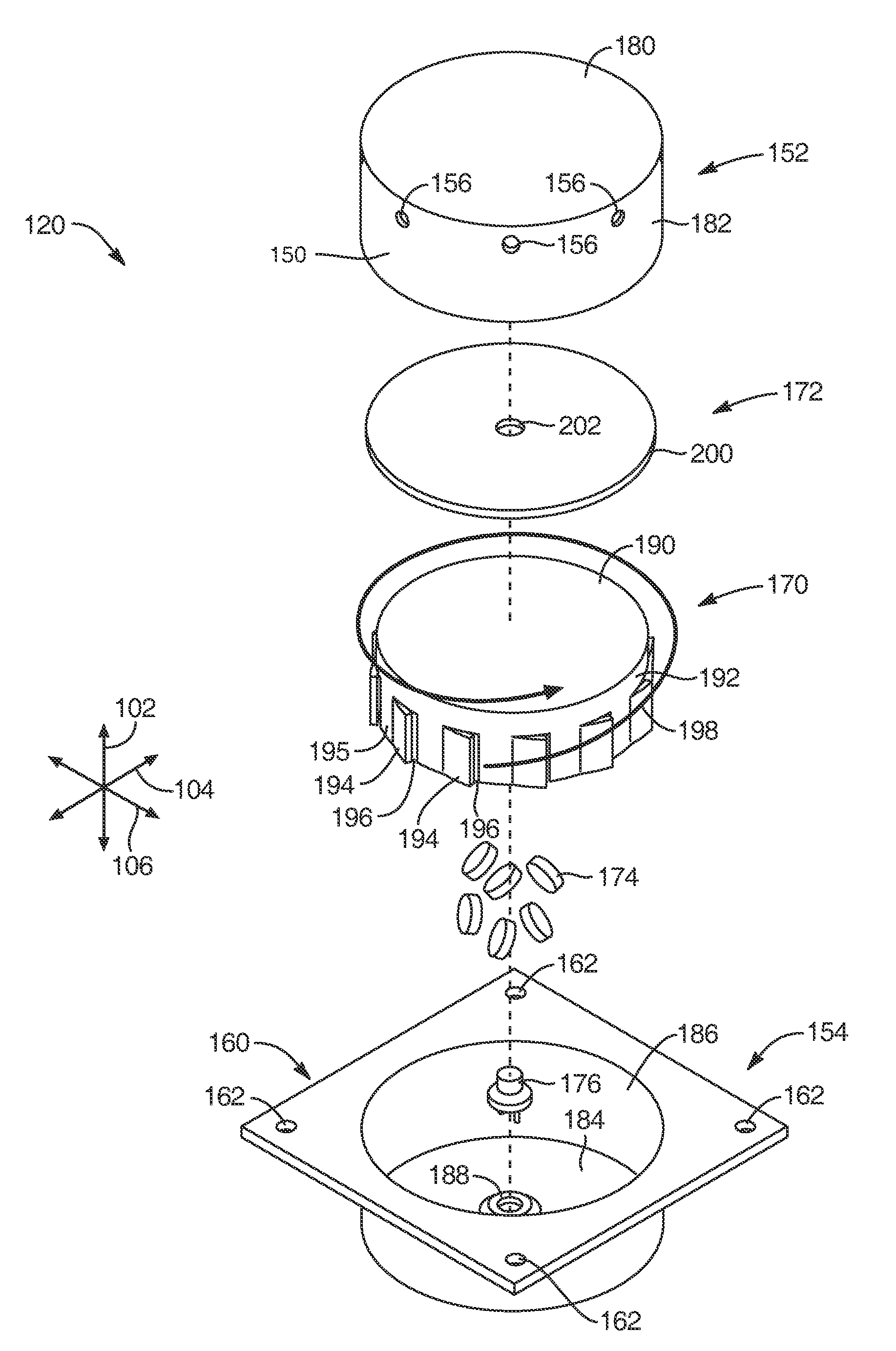
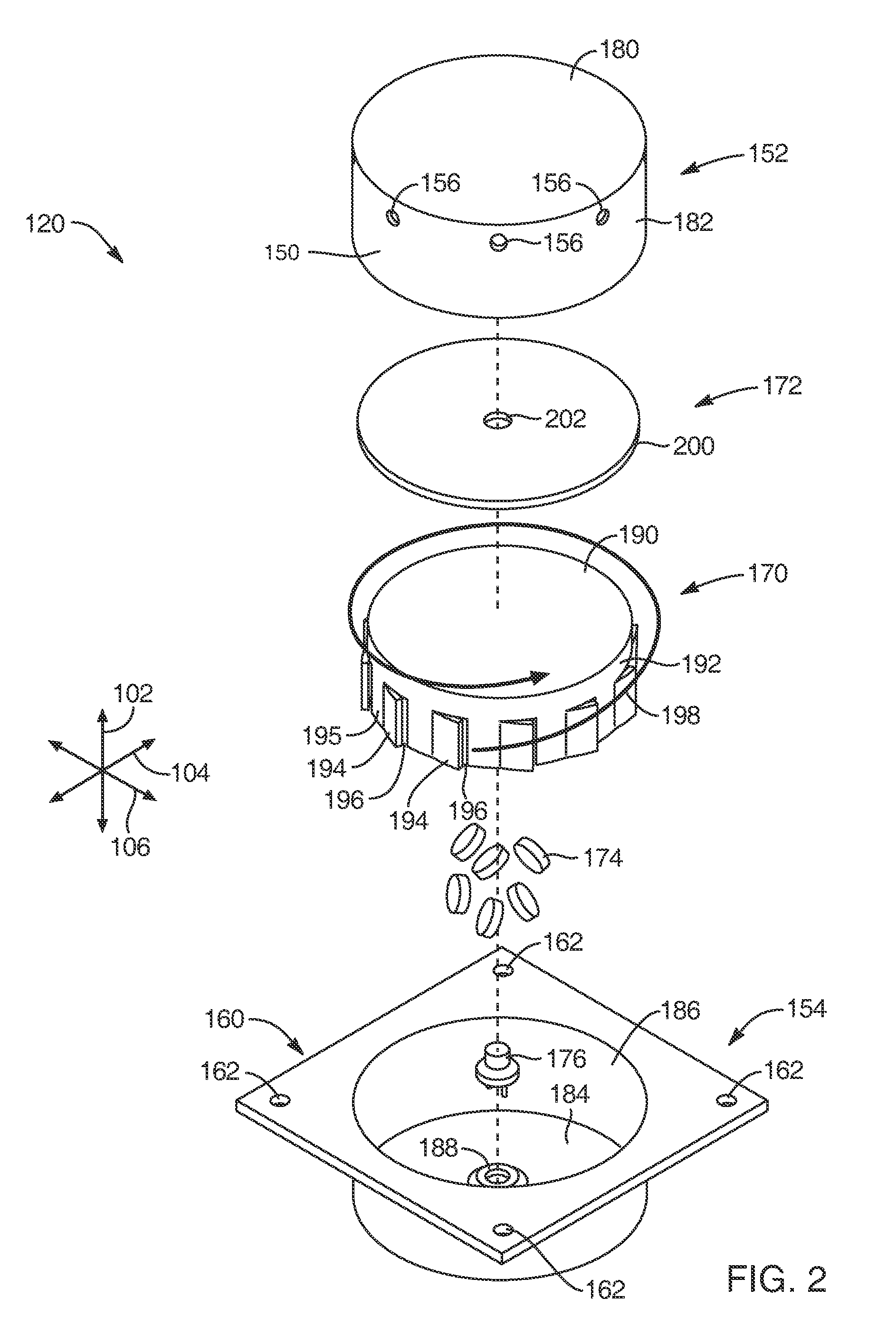
[0012]The centrifugal flow barrier may have a first opening through which the gas flows to pass through the centrifugal flow barrier. The centrifugal flow feature may have a first deflector extending from a main body of the centrifugal flow barrier proximate the first opening such that the gas impinges against the first deflector before or after passage of the gas through the first opening. In response to such impingement, the first deflector may redirect the gas to flow along the pathway. The centrifugal flow barrier may further have a plurality of additional openings and a plurality of additional deflectors, each of which is proximate one of the plurality of additional openings. The first deflector and the additional deflectors may be distributed about the longitudinal axis to relatively evenly distribute gas flow through the centrifugal flow barrier about the longitudinal axis.
[0023]The designs of the exemplary embodiments disclosed herein create a circumferential flow sufficient to filter out undesirable particles by centrifugal acceleration. Simply adding some flow vanes, however, does not necessarily assure that particles will be effectively eliminated. The circumferential flow velocities should be sufficiently high, and that can be accomplished by maintaining proper flow area ratios. Such proper ratios are a function of likely particle size, swirl velocity, gas density, drag coefficient, and centrifugal forces. As these factors vary based upon size and shape of the inflator, the type of inflation gas used, and the size of the likely impurities, a person of skill in the art, armed with this disclosure can determine the proper flow area ratios to effectively eliminate particles from the inflation gas.

Problems solved by technology

The airbag needs to deploy rapidly to be in place before motion of the vehicle occupants, but if deployment is too rapid, the result may be that the inflated airbag is too hard, thus failing to effectively cushion the occupants.
Additionally, if the gases produced by the inflator are excessively hot or entrain too much debris, damage to the airbag may result.
Each of these parts adds significantly to the cost of the inflator.
Hence, the inflator typically makes up a large portion of the cost of an airbag assembly.
The quantity of steps involved not only further increases the cost of potential inflators, it also increases the likelihood of defects in material or workmanship in the finished inflator.

Method used


Image

  • Airbag inflation systems and methods
  • Airbag inflation systems and methods
  • Airbag inflation systems and methods

Examples


Embodiment Construction

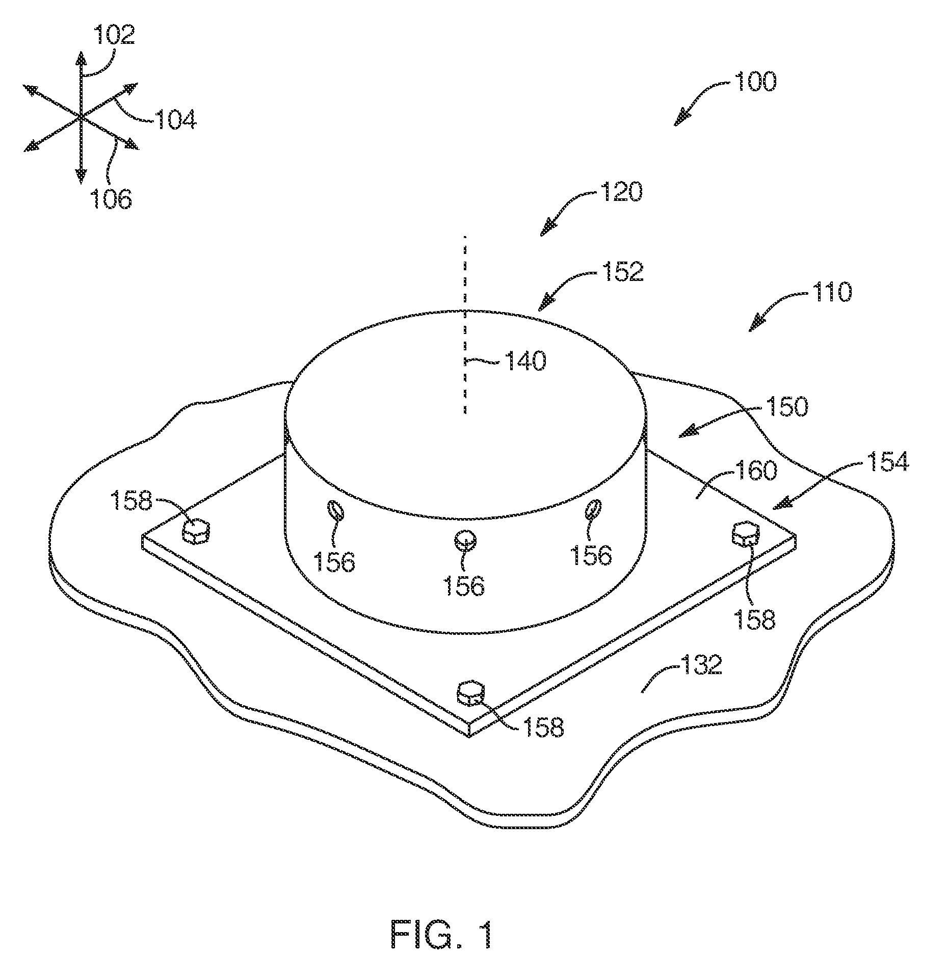
[0031]Exemplary embodiments of the present disclosure will be best understood by reference to the drawings, wherein like parts are designated by like numerals throughout. It will be readily understood that the components of the present disclosure, as generally described and illustrated in the Figures herein, could be arranged and designed in a wide variety of different configurations. Thus, the following more detailed description of the embodiments of the apparatus, system, and method of the present disclosure, as represented in FIGS. 1 through 5, is not intended to limit the scope of the invention, as claimed, but is merely representative of exemplary embodiments.

[0032]The phrases “connected to,”“coupled to” and “in communication with” refer to any form of interaction between two or more entities, including mechanical, electrical, magnetic, electromagnetic, fluid, and thermal interaction. Two components may be coupled to each other even though they are not in direct contact with ea...


PUM

PropertyMeasurementUnit
widthaaaaaaaaaa
velocityaaaaaaaaaa
shapeaaaaaaaaaa

Abstract

An airbag assembly may include an airbag and an inflator in fluid communication with the airbag. The inflator may have a gas source chamber containing a gas source and a centrifugal flow chamber into which the gas flows from the gas source chamber through a centrifugal flow barrier. As the gas moves through the centrifugal flow barrier, it may be urged to move along a pathway that encircles at least a part of a longitudinal axis of the inflator. The gas may then move toward the longitudinal axis to flow through an orifice of an inward flow barrier. this inward flow may occur at a velocity that is generally too large for entrained particulates. Thus, such particulates may remain in the centrifugal flow chamber. The gas may flow from the orifice into a plenum chamber that releases the gas to the airbag via a plurality of apertures.

Description

TECHNICAL FIELD[0001]The present invention relates to automotive safety. More specifically, the present invention relates to airbag inflators that enhance the cost-effectiveness and performance of airbag systems.BACKGROUND[0002]Inflatable safety restraint devices, or airbags, are mandatory on most new vehicles. Airbags are typically installed as part of a system with an airbag module in the steering wheel on the driver's side of car and in the dashboard on the passenger side of a car. In the event of an accident, a sensor within the vehicle measures abnormal deceleration and triggers the ignition of a charge contained within an inflator. Expanding gases from the charge travel through conduits and fill the airbags, which immediately inflate in front of the driver and passenger to protect them from harmful impact with the interior of the car. Typically, airbags are concealed within the vehicle trim to be invisible during normal vehicle operation.[0003]The inflator is a critical part o...

Claims


Application Information

Patent Timeline
Patent Type & Authority Patents(United States)
IPC IPC(8): B01D45/12B60R21/261B60R21/26
CPCB60R21/26B60R21/261B60R2021/2612B01D45/12
Inventor LAUBACHER, BRIAN A.FISCHER, CHRISTOPHER K.SMITH, BRADLEY W.
Owner AUTOLIV ASP INC
Learn More