
Engine diagnostics with skip fire control

a technology of engine diagnostics and fire control, applied in the direction of electric control, machines/engines, combustion engines, etc., can solve the problems of reducing the effectiveness of the test, the oxidizing and reducing sites are neither saturated, and the test can be difficult to run during normal engine operation

Active Publication Date: 2015-12-15
TULA TECH INC
View PDF32 Cites 31 Cited by
  • Summary
  • Abstract
  • Description
  • Claims
  • Application Information

AI Technical Summary

Benefits of technology

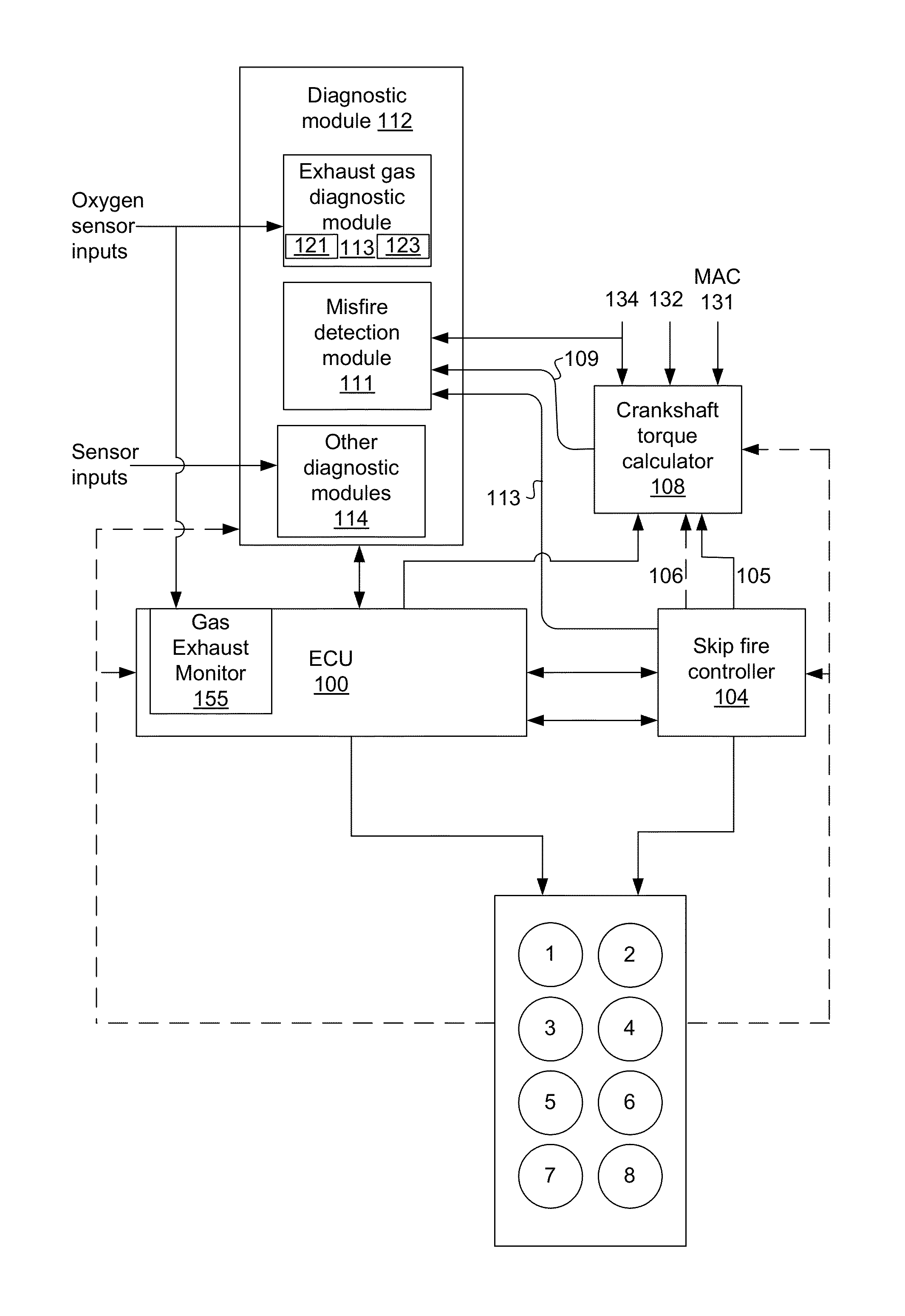
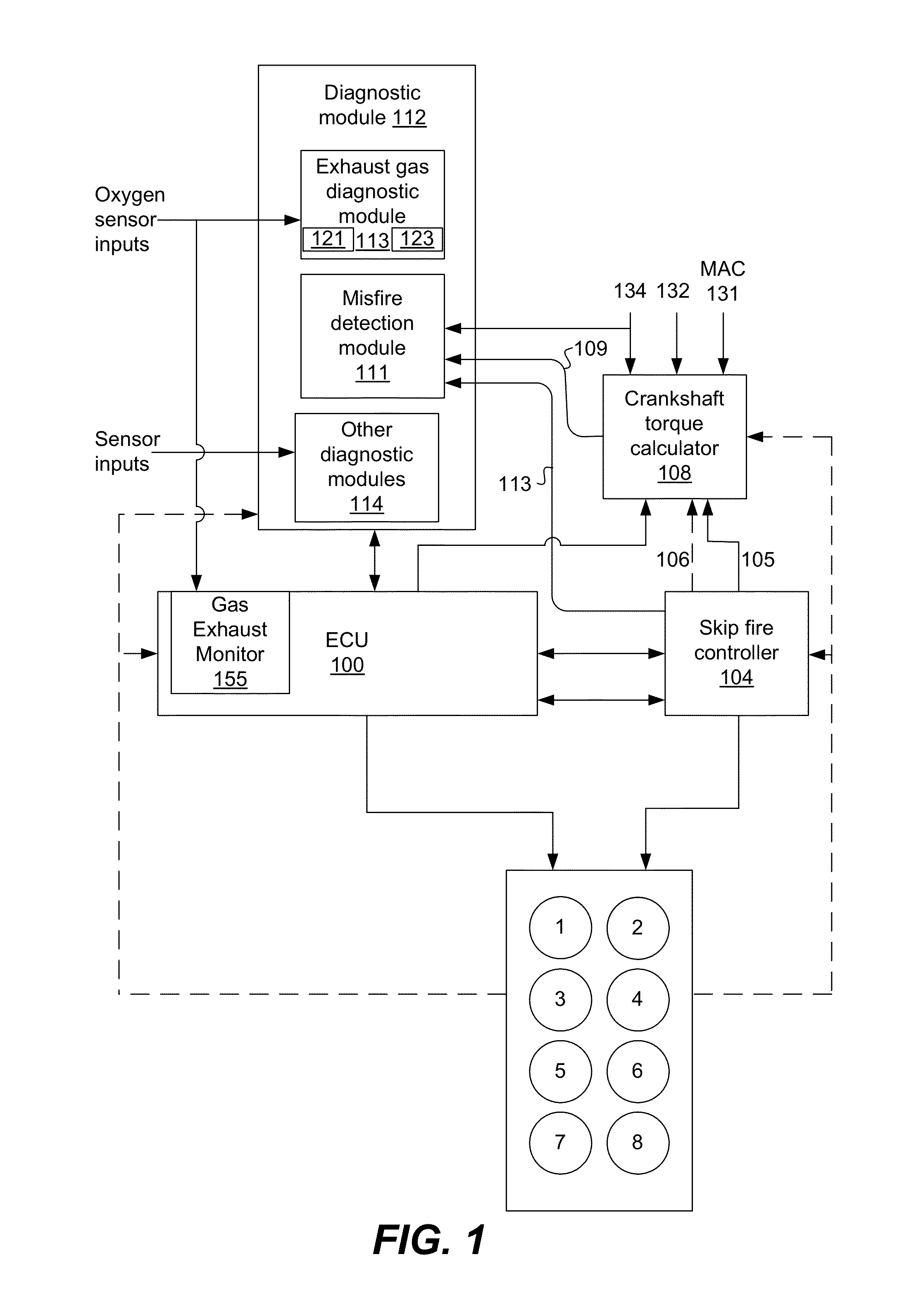
This patent describes improved methods and devices for diagnosing engine problems during operation of a vehicle. The techniques involve analyzing the engine's firing pattern to determine when to conduct certain diagnostic tests and interpret sensor inputs. The patent also describes isolating certain cylinders from neighboring cylinders to conduct diagnostics, such as fuel trim and misfire detection. The tests can be performed opportunistically or based on specific firing patterns. Control units and algorithms for conducting these tests are also described. The technical effects of this patent include improved engine diagnostics and better interpretation of sensor inputs.

Problems solved by technology

To effectively operate the catalyst must alternately be exposed to oxidizing and reducing exhaust streams, so that neither the oxidizing nor reducing sites become saturated and lose their effectiveness.
Although the concept of skip fire control has been around for a long time, it has not traditionally been used in the control of commercially available engines, so an additional challenge to implementing skip fire control is insuring that the engine's other engine / powertrain systems work effectively during skip fire control.
In practice some of these tests can be challenging to run during normal operation of the engine, in part because specific operating conditions are desired for the execution and constraining the engine to operate in a testing mode may interfere with the driver's desired operation.
Furthermore, although existing OBD systems generally work well, several of the diagnostics algorithms are not well suited for use when an engine is operated in a skip fire manner.

Method used


Image

  • Engine diagnostics with skip fire control
  • Engine diagnostics with skip fire control
  • Engine diagnostics with skip fire control

Examples


Embodiment Construction

[0023]The present invention relates generally to diagnostics in skip fire controlled engines. The skip fire controlled engines may be used to provide motive power for a vehicle.

[0024]Most modern passenger vehicles operate with four stroke, internal combustion engines. Such engines typically have a plurality of cylinders, which may be arranged in one or more banks Engine output is controlled by throttling the air flow into the engine so that all cylinders operate with substantially the same air intake level, the air intake level being reduced to reduce the engine output. Skip fire control provides a different method to control the engine output by firing some cylinders and skipping other cylinders so as to achieve the desired engine output.

[0025]Although the concept of skip fire control has been around for some time and its potential benefits with respect to fuel economy are known, to date, skip fire control has not achieved wide-spread acceptance. The applicant has developed a dynam...


PUM


Abstract

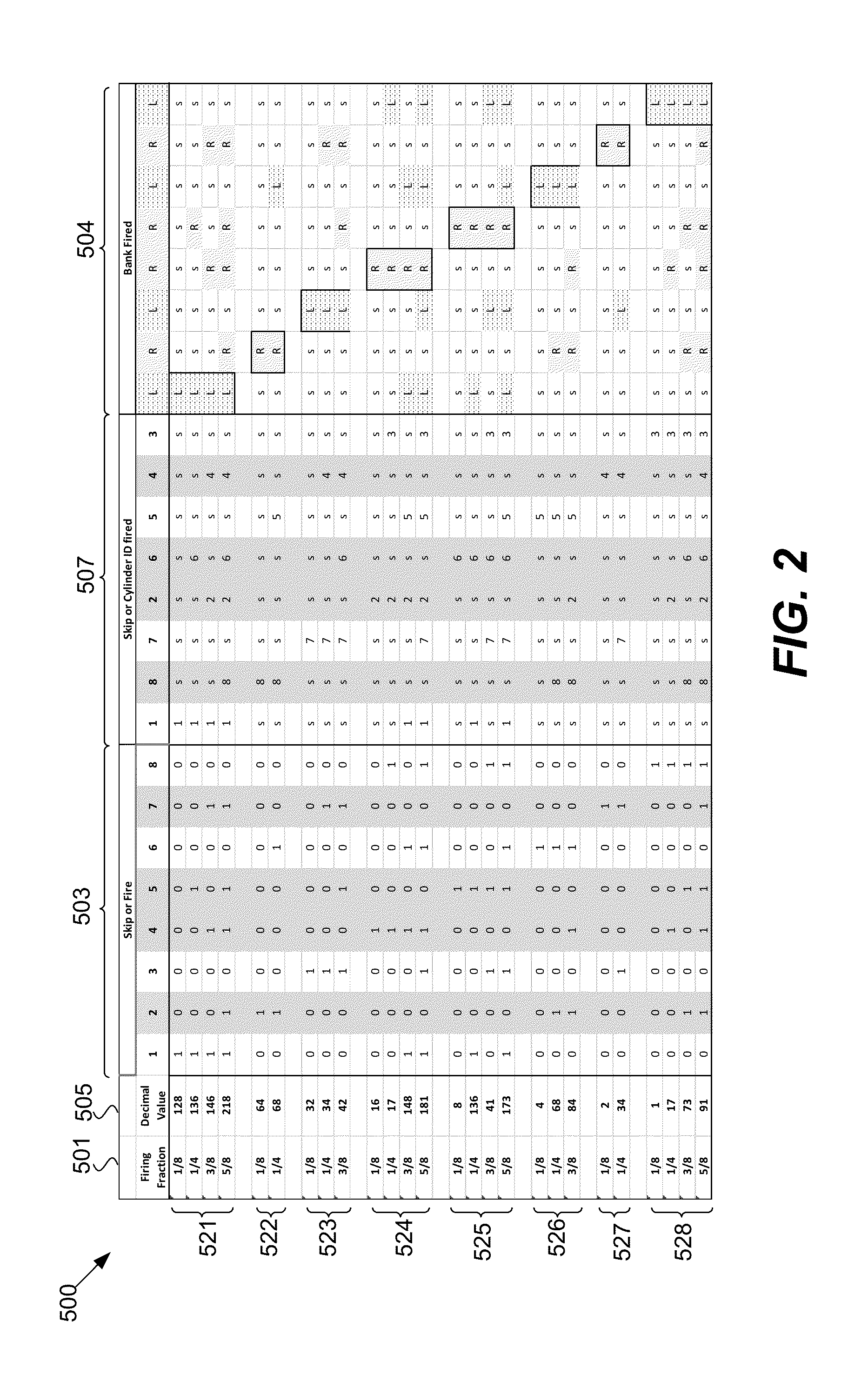
Methods and devices are described for performing engine diagnostics during skip fire operation of an engine while a vehicle is being driven. Knowledge of the firing sequence is used to determine appropriate times to conduct selected diagnostics and / or to help better interpret sensor inputs or diagnostic results. In one aspect, selected diagnostics are executed when a single cylinder is fired a plurality of times in isolation relative to a sensor used in the diagnosis. In another aspect, selected diagnostics are conducted while the engine is operated using a firing sequence that insures that no cylinders in a first cylinder bank are fired for a plurality of engine cycles while cylinders in a second bank are at least sometimes fired. The described tests can be conducted opportunistically, when conditions are appropriate, or specific firing sequences can be commanded to achieve the desired isolation or skipping of one or more selected cylinders.

Description

RELATED APPLICATIONS[0001]This application claims priority of U.S. Provisional Application No. 61 / 799,180, filed Mar. 15, 2013, which is incorporated herein by reference.BACKGROUND OF THE INVENTION[0002]The present invention relates generally to powertrain diagnostics conducted during skip fire control of an internal combustion engine.[0003]Skip fire engine control is understood to offer a number of benefits including the potential of increased fuel efficiency. In general, skip fire engine control contemplates selectively skipping the firing of certain cylinders during selected firing opportunities. Thus, for example, a particular cylinder may be fired during one firing opportunity and then may be skipped during the next firing opportunity and then selectively skipped or fired during the next. This is contrasted with conventional variable displacement engine operation in which a fixed set of the cylinders are deactivated during certain low-load operating conditions.[0004]When a cyli...

Claims


Application Information

Patent Timeline
Patent Type & Authority Patents(United States)
IPC IPC(8): F02D17/02F02D17/00F02D37/02F02D41/00F02D41/20
CPCF02D17/02F02D17/00F02D37/02F02D41/00F02D41/0087F02D2041/2027F02D2250/18Y02T10/44Y02T10/40F02D41/0082F02D41/0235
Inventor CHEN, SHIKUI KEVINYUAN, XINSWITKES, JOSHUA P.CARLSON, STEVEN E.SHOST, MARK A.
Owner TULA TECH INC
Learn More