
Damage proxy map from interferometric synthetic aperture radar coherence

a synthetic aperture and proxy map technology, applied in the field of damage assessment, can solve the problems of building collapse, claiming the lives of many, and building collapse, and achieve the effect of suppressing background clutter

Active Publication Date: 2015-12-08
CALIFORNIA INST OF TECH
View PDF1 Cites 0 Cited by
  • Summary
  • Abstract
  • Description
  • Claims
  • Application Information

AI Technical Summary

Benefits of technology

[0023]Embodiments of the invention provide a methodology that produces reliable damage proxy maps of building damage using InSAR coherence even in the presence of other decorrelation sources that are coupled to each other. The processed image of coherence change is referred to herein as a DPM, because it is derived from remotely sensed data without ground truth validation.
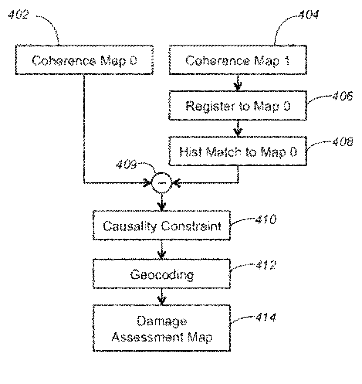
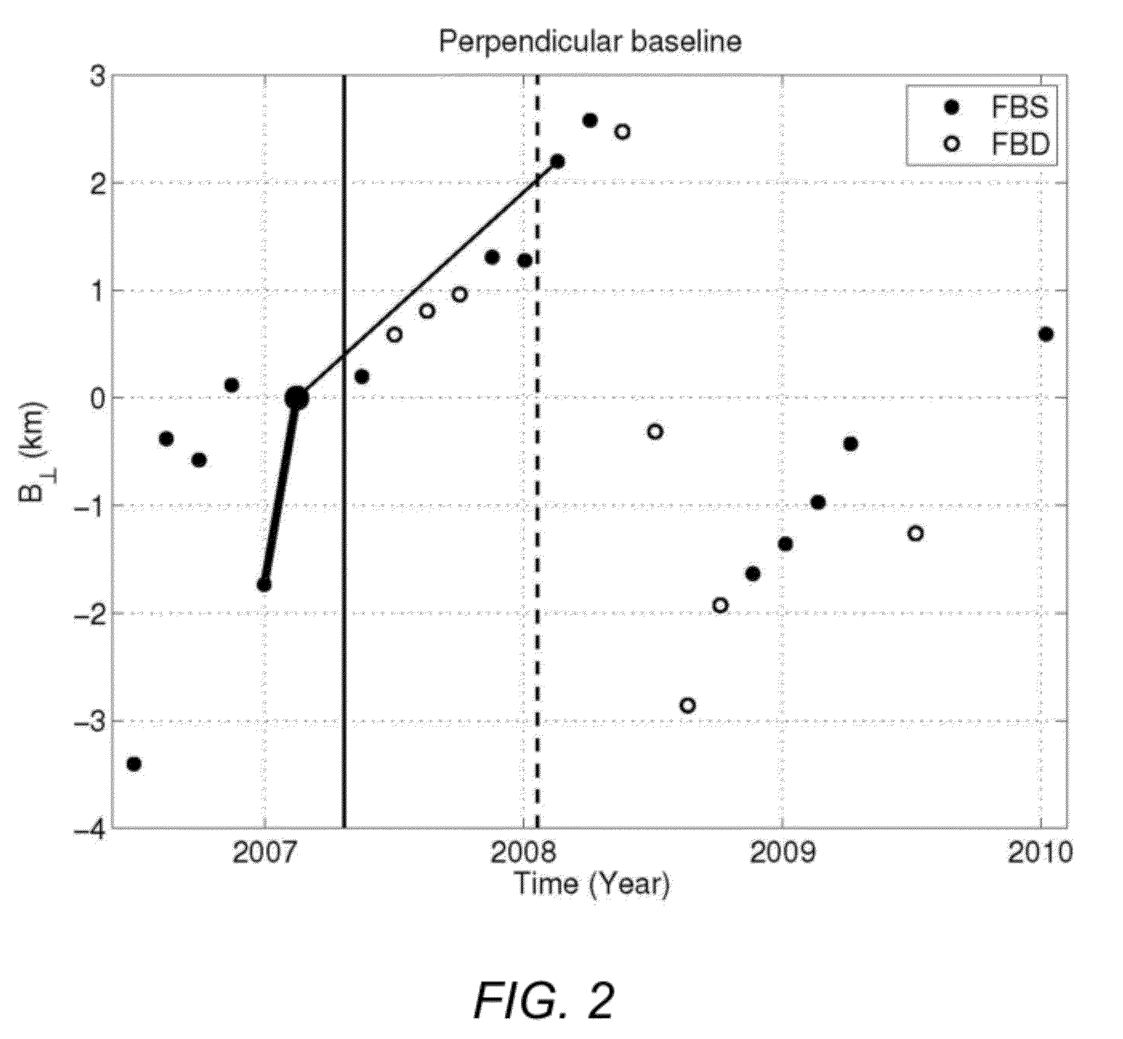
[0024]The methodology produces robust damage maps despite the different perpendicular and temporal baseline conditions, using histogram matching and causality constraints. Three radar images are used to make two pairs of interferometric coherence maps, one pair before the damage (master pair) and the other pair spanning the damage (slave pair). The radar image processing is done using ROI PAC (Repeat Orbit Interferometry PACkage), an InSAR processing software package available from the assignee of the present invention or other InSAR processing software. The slave coherence map is registered to the master coherence map using cross-correlation of their amplitude images. Then the pixel values of the slave coherence map are modified using a histogram-matching algorithm, so that the histogram of the slave coherence exactly matches that of the master coherence. A causality constraint is applied to suppress background clutter. The resulting damage map is transformed onto a georeferenced coordinate system and overlaid on top of a virtual mapping and geographic information program (e.g., Google™ Earth) for easy interpretation.

Problems solved by technology

Major earthquakes cause buildings to collapse, often claiming the lives of many.
Earthquakes of significant magnitude cause buildings to collapse, often claiming the lives of many.
For example, the 2010 Mw 7.0 Haiti earthquake killed about 230,000 people, with large uncertainty in the death toll, causing about 280,000 buildings to collapse or be severely damaged [1].
More recently, the February 2011 Mw 6.3 Christchurch earthquake killed 185 people and caused a wide range of building damage and extensive liquefaction damage with about 400,000 tons of silt.
The majority of casualties are in cities, but the extent of damage to smaller towns and villages can be even more difficult to assess, especially on short time scales, because communications networks are frequently damaged and ineffective.
However, operational use of remote sensing data for disaster response, especially for earthquakes, volcanic eruptions, landslides, and tsunamis, has not yet been effectively put into practice.
However, automation of these processes is still an active research area, and an optimal methodology both for the mapping and the subsequent data integration and processing has yet to be developed [8].
Major damage to a building significantly increases the interferometric phase variance in the impacted resolution element.
Building damage is often much more localized than lava flow and surface rupture.
Moreover, damaged buildings are often surrounded by other decorrelation sources such as changes in vegetation during the time span of interferometric pair.
This background variability makes it difficult to isolate building damage decorrelation in a single coherence map.
These inherent couplings of different decorrelation sources challenge the ability to isolate coherence change due to building damage.

Method used


Image

  • Damage proxy map from interferometric synthetic aperture radar coherence
  • Damage proxy map from interferometric synthetic aperture radar coherence
  • Damage proxy map from interferometric synthetic aperture radar coherence

Examples


Embodiment Construction

[0038]In the following description, reference is made to the accompanying drawings which form a part hereof, and which is shown, by way of illustration, several embodiments of the present invention. It is understood that other embodiments may be utilized and structural changes may be made without departing from the scope of the present invention.

Overview

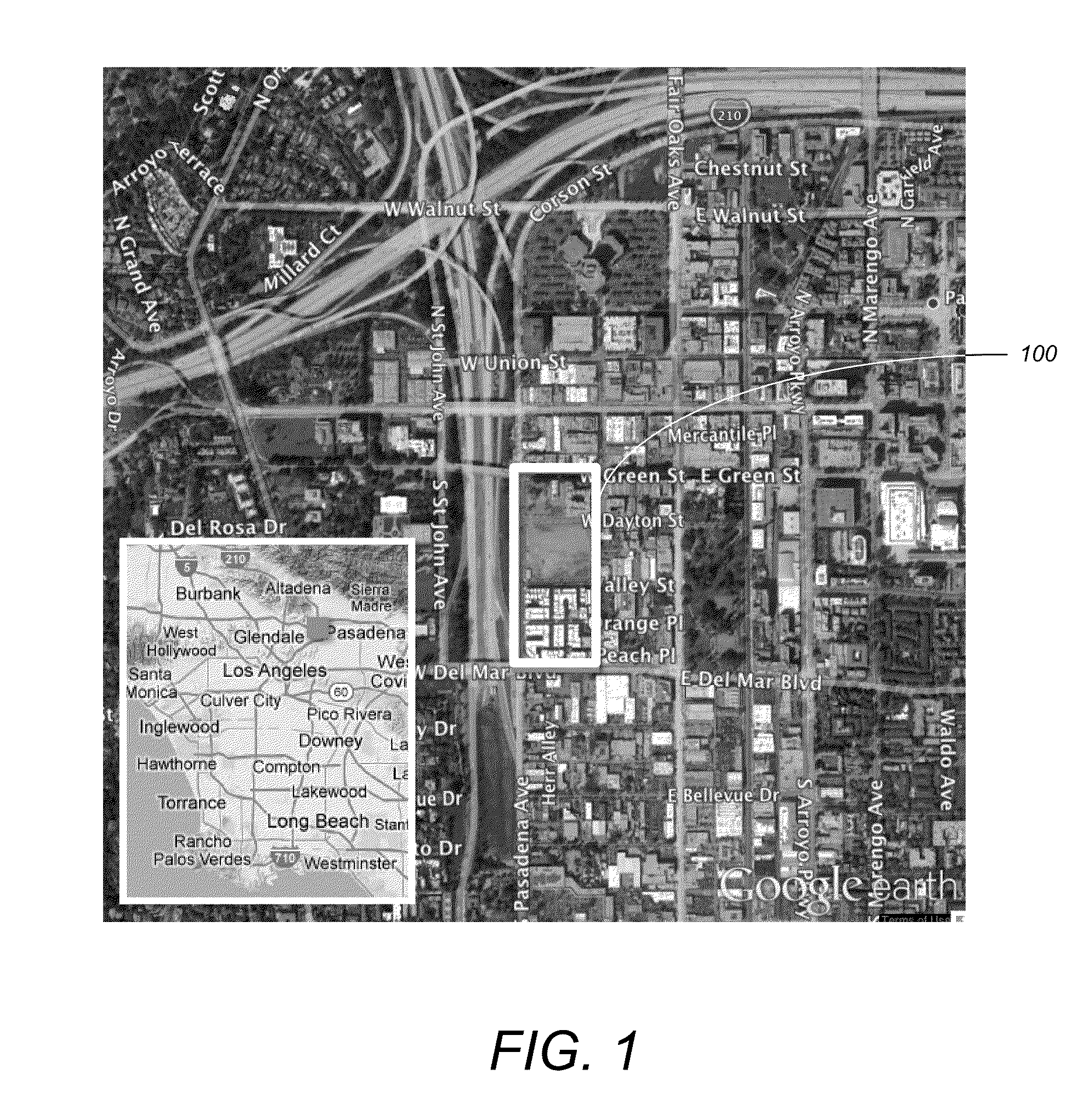
[0039]Embodiments of the invention provide a methodology that produces robust damage maps. As an example, embodiments of the invention were used to detect a building demolition project in downtown Pasadena, where 2.5 building blocks were demolished for new apartment complex. The results show clear detection of the demolition site both in space and in time. The anomalous signal starts showing up immediately after the building demolition began and clearly shows up as red blobs in the damage map. During the demolition period, the signal-to-noise ratio at the demolition site increased about 100 times. The developed methodology produced a...


PUM


Abstract

A method, apparatus, and article of manufacture provide the ability to generate a damage proxy map. A master coherence map and a slave coherence map, for an area prior and subsequent to (including) a damage event are obtained. The slave coherence map is registered to the master coherence map. Pixel values of the slave coherence map are modified using histogram matching to provide a first histogram of the master coherence map that exactly matches a second histogram of the slave coherence map. A coherence difference between the slave coherence map and the master coherence map is computed to produce a damage proxy map. The damage proxy map is displayed with the coherence difference displayed in a visually distinguishable manner.

Description

CROSS-REFERENCE TO RELATED APPLICATIONS[0001]This application claims the benefit under 35 U.S.C. Section 119(e) of the following commonly-assigned U.S. provisional patent application(s), which is / are incorporated by reference herein:[0002]Provisional Application Ser. No. 61 / 498,755, filed on Jun. 20, 2011, by Sang Ho Yun, Eric J. Fielding, Frank H. Webb, and Mark Simons, entitled “Damage Proxy Map from InSAR Coherence,”.STATEMENT REGARDING FEDERALLY SPONSORED RESEARCH AND DEVELOPMENT[0003]The invention described herein was made in the performance of work under a NASA Contract, and is subject to the provisions of Public Law 96-517 (35 USC 202) in which the contractor has elected to retain title.BACKGROUND OF THE INVENTION[0004]1. Field of the Invention[0005]The present invention relates generally to damage assessment, and in particular, to a method, apparatus, and article of manufacture for generating a damage proxy map from radar signals.[0006]2. Description of the Related Art[0007]...

Claims


Application Information

Patent Timeline
Patent Type & Authority Patents(United States)
IPC IPC(8): G01S13/90
CPCG01S13/9023
Inventor YUN, SANG-HOFIELDING, ERIC JAMESONWEBB, FRANK H.SIMONS, MARK
Owner CALIFORNIA INST OF TECH
Learn More