
LED elevated light fixture and method

a technology of light fixtures and elevated beams, applied in the field of airfield light fixtures, can solve the problems of significant power requirements for operation of sources and easy damag

Active Publication Date: 2015-12-08
HUGHEY & PHILLIPS
View PDF5 Cites 17 Cited by
  • Summary
  • Abstract
  • Description
  • Claims
  • Application Information

AI Technical Summary

Benefits of technology

The present invention is an elevated light for an airfield that includes a substrate, two or more LEDs, a reflector, and an LED driver circuit. The LEDs are mounted on the substrate and connected in series. The reflector is affixed to the substrate and reflects light emitted from the LEDs radially. The LED driver circuit provides current to the LEDs and detects failure of one or more LEDs by detecting a voltage drop. The elevated light may also have a baffle to filter light emitted from the LEDs and an optically transmissive cover to filter light emitted from the LEDs. The invention also includes a method of maintaining illumination in the elevated light by orienting the LEDs and reflector, providing an electrical current, detecting voltage changes, and altering the provided electrical current. The technical effects of the invention include improved illumination in the airfield and a more reliable and efficient elevated light system.

Problems solved by technology

However, such conventional light sources require significant power for operation (e.g., 45 W per fixture) and are susceptible to damage caused by, for example, vibration.

Method used


Image

  • LED elevated light fixture and method
  • LED elevated light fixture and method
  • LED elevated light fixture and method

Examples


Embodiment Construction

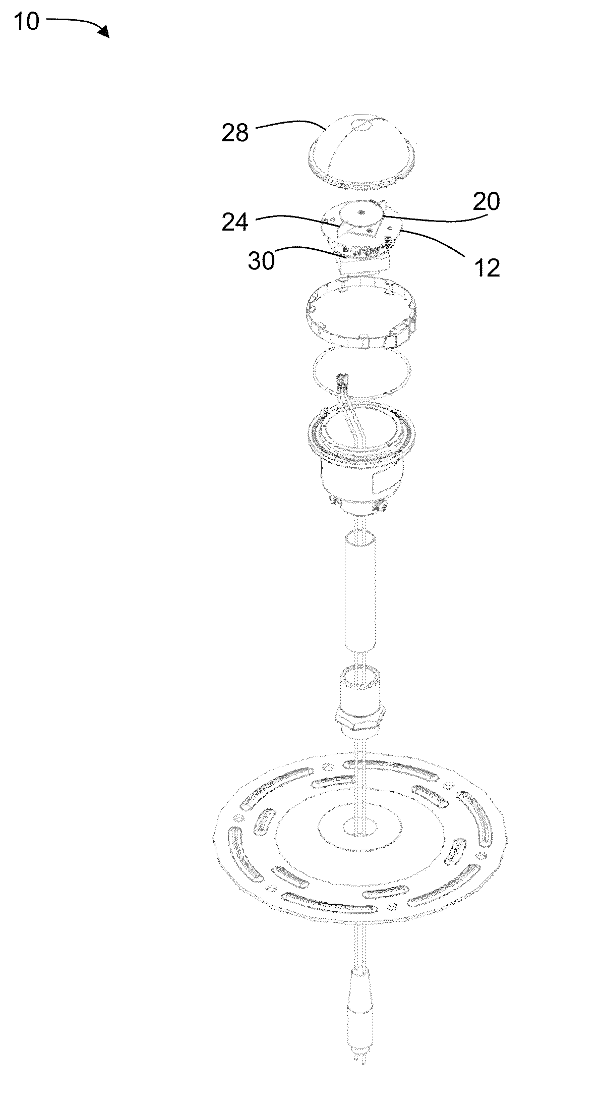
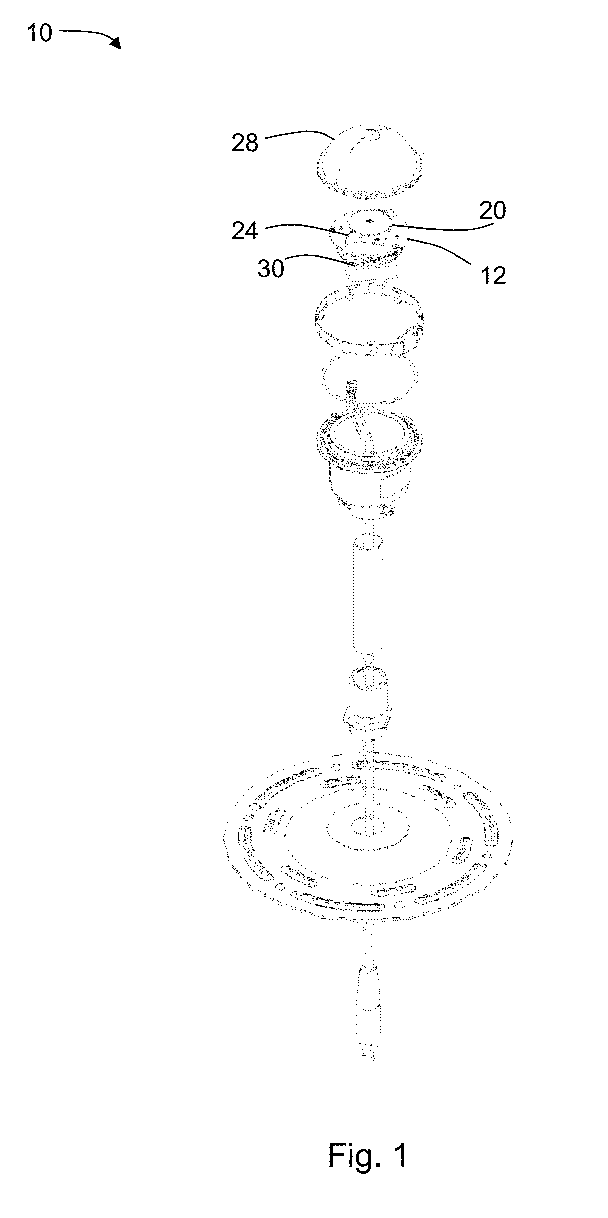
[0028]Referring now to FIG. 4, the present disclosure may be embodied as an elevated light 10 for an airfield. Such light fixtures are known for use in delineating the edges of airfield runways, thresholds, and taxiways. The light 10 may be generally configured as a pedestal light wherein a housing 6 of the light is elongate in order to elevate the illuminating portion 8 of the light 10 above the ground. In this configuration, the light 10 may be considered to have a longitudinal axis 9. The disclosed light 10 has light-emitting diode (“LED”) illumination such that improvements may be achieved in required power (reduced) and reliability (increased) over conventional elevated lighting.

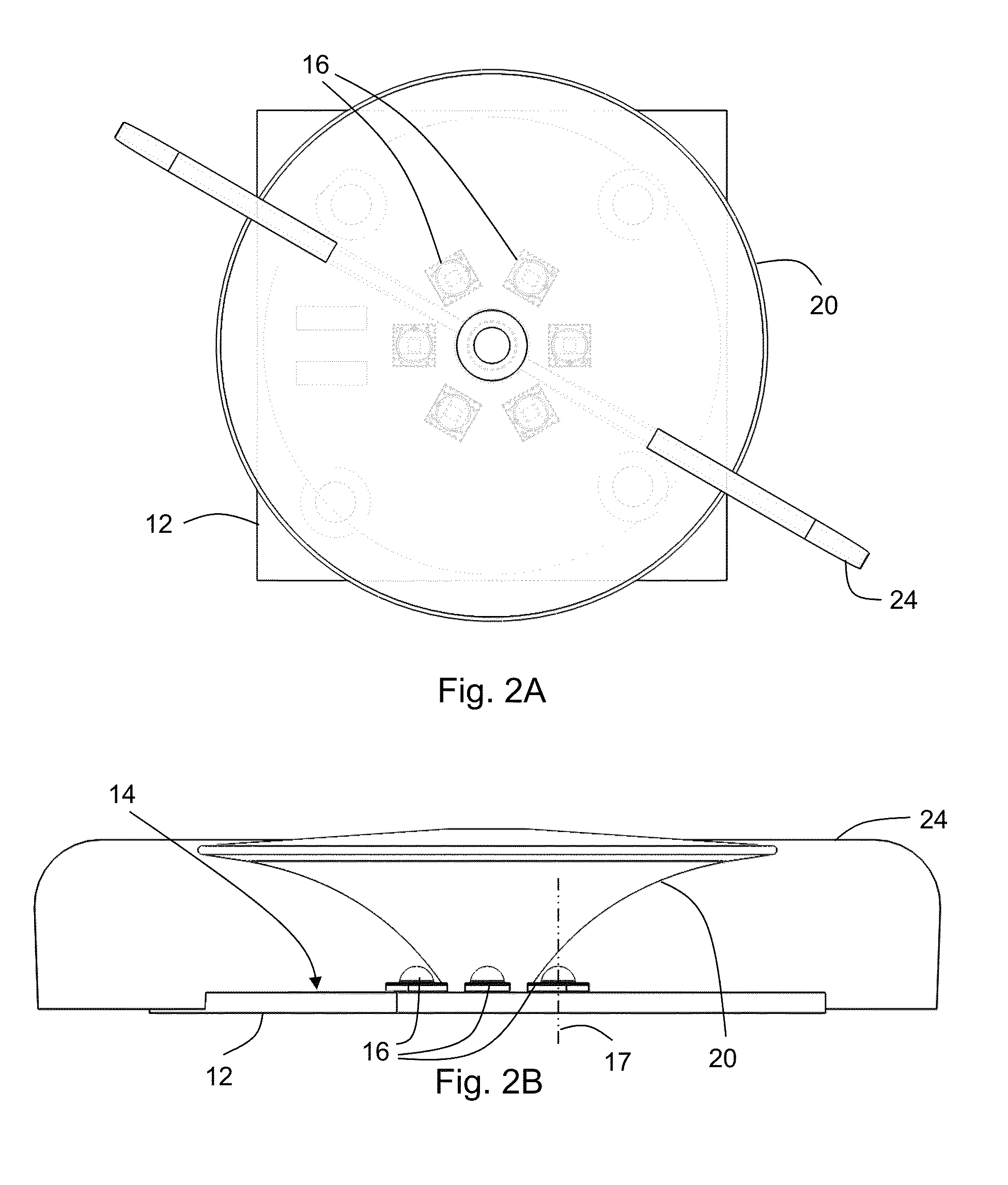
[0029]With reference to FIGS. 2A and 2B, the light 10 has a substrate12 with a mounting surface 14. Two or more LEDs 16 are mounted to the mounting surface of the substrate 12. Each LED 16 has a primary illumination axis 17 which is defined along a direction perpendicular to the LED's 16 mounting struct...


PUM


Abstract

Disclosed are elevated lights and methods of maintaining illumination in elevated lights for an airfield. The elevated lights have a substrate having a mounting surface, LEDs, a reflector, and an LED driver circuit. The LEDs are disposed on the mounting surface of the substrate and configured such that a primary illumination axis of each LED is oriented along a longitudinal axis of the elevated light. The reflector is configured such that the light emitted from the LEDs is reflected radially with respect to the longitudinal axis of the elevated light. The driver circuit is configured to provide a current to the LEDs and detect failure of one or more of the LEDs. Illumination is maintained by providing a current to the LEDs, detecting a voltage change across the LEDs, determining, based on the voltage change, LED failure, and altering the provided electrical current in order to maintain illumination.

Description

CROSS-REFERENCE TO RELATED APPLICATIONS[0001]This application claims priority to U.S. Provisional Application No. 61 / 911,267, filed on Dec. 3, 2013, the disclosure of which is incorporated herein by reference.FIELD OF THE INVENTION[0002]The invention relates to airfield light fixtures.BACKGROUND OF THE INVENTION[0003]Elevated light fixtures are commonly used in airfield lighting to delineate runways, taxiways, thresholds, etc. Such uses of light fixtures may require certification of compliance with governmental specifications such as the U.S. Federal Aviation Administration's “Specification for Runway and Taxiway Light Fixtures” (AC 150 / 5345-46). Previous elevated lighting often utilized quartz-halogen or other conventional light sources. However, such conventional light sources require significant power for operation (e.g., 45 W per fixture) and are susceptible to damage caused by, for example, vibration. As such, there is a need for more resilient light fixtures that are able to m...

Claims


Application Information

Patent Timeline
Patent Type & Authority Patents(United States)
IPC IPC(8): H05B37/02F21V13/10F21V13/08F21V7/04H05B33/08F21W111/06F21Y101/02H05B44/00
CPCF21V13/10H05B33/089F21V7/04F21V13/08F21W2111/06F21Y2101/02F21S8/083F21V7/0008F21V7/0058F21Y2115/10F21Y2103/33F21Y2113/13H05B47/24H05B45/54
Inventor BASTIANI, SERGIOBROWN, JEROME
Owner HUGHEY & PHILLIPS
Learn More