
Seal ring

a sealing ring and sealing technology, applied in the field of sealing ring, can solve the problems of reducing the capacity of the oil pump, reducing the drive loss of the automatic transmission, and reducing the oil pump capacity, so as to improve the oil squeezing effect, increase the lift, and achieve the effect of reducing friction

Active Publication Date: 2015-12-08
RIKEN CO LTD
View PDF26 Cites 5 Cited by
  • Summary
  • Abstract
  • Description
  • Claims
  • Application Information

AI Technical Summary

Benefits of technology

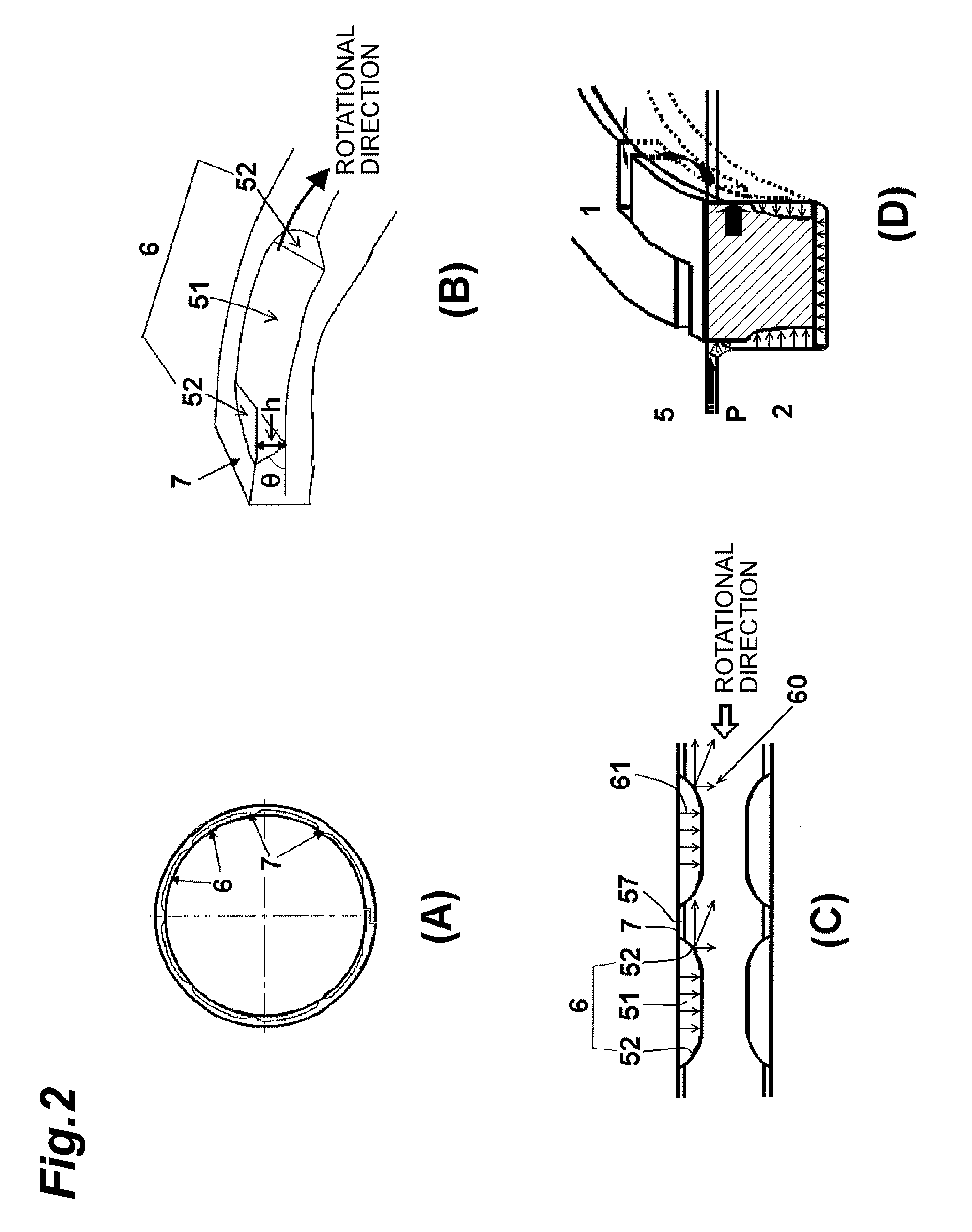
[0013]In the present invention, the recessed sections circumferentially spaced apart from each other with pillar sections interposed therebetween are provided on the inner peripheral side of the contact-side surface. The circumferential opposite ends of each of the recessed sections are formed as squeezing portions formed of curved surfaces convex toward the pillar sections. The pillar sections and the recessed sections are connected with each other through a gentle R shape, thereby improving the oil squeezing effect and increasing the lift. The friction can thus be effectively reduced. The seal ring of the present invention can also prevent oil leakage because the contact-side surface and the ring groove side surface are in surface contact. The seal ring of the present invention has both low friction characteristics and low leakage characteristics and therefore can effectively reduce the drive loss of the automatic transmission.

Problems solved by technology

However, the friction loss of the seal ring leads to the drive loss of the automatic transmission.
In addition, the capacity of an oil pump of the automatic transmission is a significant factor that causes the drive loss.
There is therefore a demand for reducing the amount of oil leakage from the seal ring thereby reducing the capacity of the oil pump.
As a result, the oil leaks from the gap of the abutment joint.

Method used


Image

  • Seal ring
  • Seal ring
  • Seal ring

Examples


example 1

[0039]A seal ring having a recessed section structure shown in FIG. 3A was produced by injection molding using a PEEK material including carbon fibers added thereto. Eight recessed sections each having a deepest portion of 0.22 mm in depth and a circumferential width of 24 mm were formed on each of the contact-side face and the pressure-receiving surface, where the curvature of the squeezing portion was R40. The outer diameter (nominal diameter) of the seal ring was 67 mm, the thickness (radial width) thereof was 2.3 mm, and the width (axial width) thereof was 2.32 mm. The abutment joint was a triple step abutment joint shown in FIG. 5. The depth of the deepest portion was 9.5 where the axial width of the seal ring was 100. The circumferential width of the deepest portion was 16.9 where the circumferential length of one recessed section was 100. The droop length of the R curved surface of the squeezing portion was 13.9 where the sum of the circumferential widths of the squeezing por...

examples 2 to 5

[0046]Seal rings having a recessed section structure shown in FIG. 3A were produced by injection molding using a PEEK material including carbon fibers added thereto, in a similar manner as in Example 1. Here, the curvature of the squeezing portion was changed such that the depth “h” of the deepest portion was 0.03 mm (Example 2), 0.08 mm (Example 3), 0.12 mm (Example 4), and 0.41 mm (Example 5). The outer diameter (nominal diameter) of the seal ring was 67 mm, the thickness (radial width) thereof was 2.3 mm, and the width (axial width) thereof was 2.32 mm. The abutment joint was a triple step abutment joint shown in FIG. 5. The depth of the deepest portion of Examples was 1.3 (Example 2), 3.4 (Example 3), 5.2 (Example 4), and 17.7 (Example 5) where the axial width of the seal ring was 100. The friction and the amount of oil leakage of the resultant seal rings were measured in a similar manner as in Example 1.

[0047]The relations between the depth “h” of the deepest portion and fricti...

examples 6 to 10

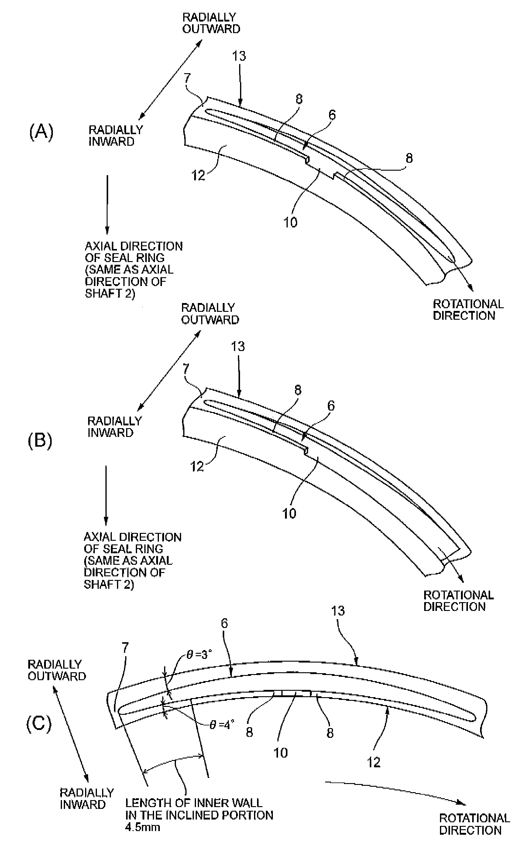
[0050]Seal rings having a recessed section structure shown in FIG. 4A were produced by injection molding using a PEEK material including carbon fibers added thereto. Inner walls having a width of 0.3 mm and a circumferential length of 10 mm for each side were provided from the opposite ends of each of the recessed sections toward the center along the inner peripheral end, and an oil introduction opening having a circumferential length of 4 mm was formed at the center. Here, the seal rings were produced with the curvature of the squeezing portion being changed such that the depth “h” of the deepest portion was 0.03 mm (Example 6), 0.08 mm (Example 7), 0.12 mm (Example 8), 0.22 mm (Example 9), and 0.41 mm (Example 10). The outer diameter (nominal diameter) of the seal ring was 67 mm, the thickness (radial width) thereof was 2.3 mm, and the width (axial width) thereof was 2.32 mm. The abutment joint was a triple step abutment joint shown in FIG. 5. The friction and the amount of oil le...


PUM


Abstract

Provided is a seal ring which has low-friction characteristics and low-leakage characteristics, reduces drive loss of the automatic transmission of an automobile, and contributes to improvement in fuel consumption of the automobile. The seal ring is attached to a shaft groove on the outer peripheral surface of a shaft. A plurality of recessed sections circumferentially spaced apart from each other with pillar sections interposed therebetween are formed at least on the inner peripheral side of a side surface of the seal ring in contact with the shaft groove. The circumferential opposite ends of each of the recessed sections are formed as squeezing portions formed of curved surfaces convex toward the pillar sections. The depth “h” of a deepest portion in which the axial width of the recessed section is the largest is set in the range of 2 to 17 where the axial width of the seal ring is 100.

Description

RELATED APPLICATIONS[0001]The present application is a National Phase of International Application Number PCT / JP2012 / 082975, filed Dec. 19, 2012, and claims priority from, Japanese Application Number 2011-282480, filed Dec. 23, 2011.TECHNICAL FIELD[0002]The present invention relates to a seal ring and more particularly to a seal ring for use in hydraulic equipment such as automatic transmissions of automobiles.BACKGROUND ART[0003]In recent years, there is a demand for reducing the drive loss of automatic transmissions of automobiles in order to improve the fuel consumption of the automobiles. For the purpose of hydraulic sealing, a seal ring is attached to an automatic transmission. However, the friction loss of the seal ring leads to the drive loss of the automatic transmission. To reduce friction of the seal ring is therefore an important task. In addition, the capacity of an oil pump of the automatic transmission is a significant factor that causes the drive loss. There is theref...

Claims


Application Information

Patent Timeline
Patent Type & Authority Patents(United States)
IPC IPC(8): F16J9/12F16J15/34F16J15/16F16J15/32F16J15/44F16J15/46
CPCF16J15/3448F16J15/164F16J15/3272F16J15/441F16J15/18
Inventor NAGAI, JUNYASAITO, MIKASHIBANO, TOMOYA
Owner RIKEN CO LTD
Learn More