
Method for the guidance of a rotorcraft, which method limits noise discomfort in a procedure for the approach to a landing point

a rotorcraft and noise discomfort technology, applied in the direction of vehicle position/course/altitude control, process and machine control, instruments, etc., can solve the problems of limited noise discomfort and particularly noticeable noise discomfort generated by rotorcraft during the approach phase to, or during the departure phase from, a landing point, etc., to achieve the effect of optimizing the reduction of noise discomfor

Active Publication Date: 2015-12-08
EUROCOPTER
View PDF23 Cites 3 Cited by
  • Summary
  • Abstract
  • Description
  • Claims
  • Application Information

AI Technical Summary

Benefits of technology

The system significantly reduces noise discomfort by optimizing the approach trajectory based on real-time wind data and noise-abatement criteria, ensuring reduced noise levels during the landing phase while maintaining safe and stable flight.

Problems solved by technology

The noise discomfort generated by rotorcraft are particularly noticeable during the landing phase, because of the operational mode of the rotor during the descent phase of the rotorcraft and because of the position of the rotorcraft as it approaches the ground.
It is known that the noise discomfort produced by a rotorcraft during the approach phase to, or during the departure phase from, a landing point can be limited.

Method used


Image

  • Method for the guidance of a rotorcraft, which method limits noise discomfort in a procedure for the approach to a landing point
  • Method for the guidance of a rotorcraft, which method limits noise discomfort in a procedure for the approach to a landing point
  • Method for the guidance of a rotorcraft, which method limits noise discomfort in a procedure for the approach to a landing point

Examples


Embodiment Construction

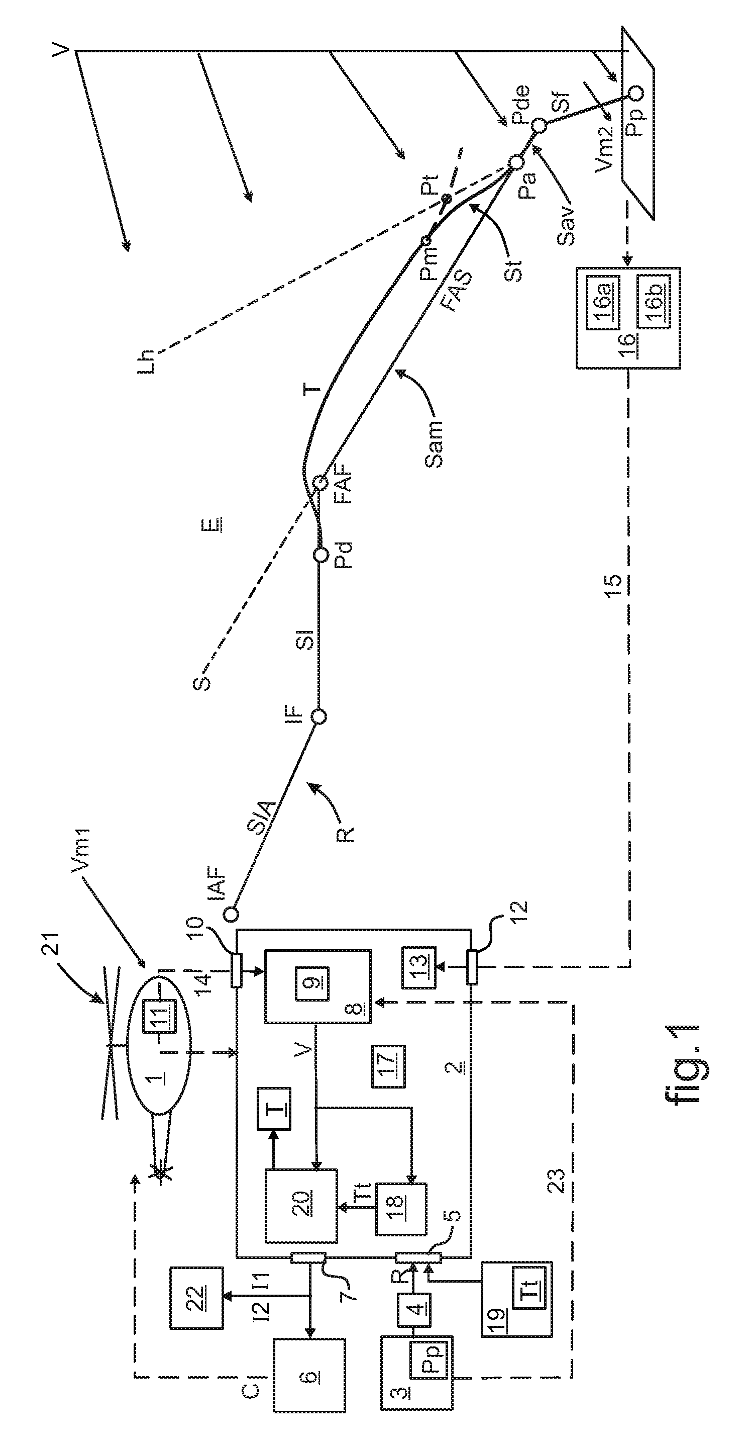
[0096]In FIG. 1, a rotorcraft (1) is on approach to a landing point (Pp)—specifically, a heliport or a helicopter pad. The rotorcraft (1) has computing means (2) for calculating an approach trajectory (T) that should be followed by the rotorcraft (1), in accordance with a predefined approach route (R). The approach route (R) is taken from an aeronautical database (3) that stores a plurality of landing points (Pp). At least one specific approach route (R) is associated with each of the stored landing points (Pp), with the said approach route (R) defining various waypoints for the rotorcraft (1).

[0097]In order to extract from the aeronautical database (3) the approach route (R) to be taken into consideration, the pilot has means (4) for selecting the correct approach route (R) to the landing point (Pp) toward which the rotorcraft (1) is on approach. The computation means (2) are linked to the aeronautical database (3) by means of a first communications interface (5) that allows the sa...


PUM


Abstract

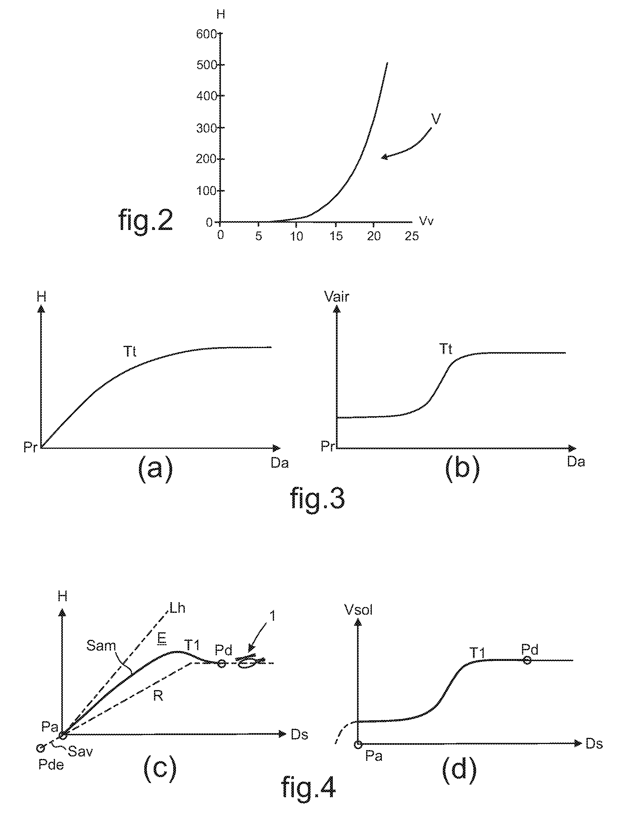
A method for the guidance of a rotorcraft (1) in relation to a landing point (Pp) in accordance with a landing procedure. An approach route (R) is identified and an approach trajectory (T) is calculated in accordance with a ground slope (S) imposed by the approach route (R). An upstream segment (Sam) of the approach trajectory (T) is calculated through the application of a typical trajectory, as defined in accordance with the ground slope (S), the current mass of the rotorcraft (1), and a low-noise or noise-abatement criterion relating to the noise discomfort generated by the rotorcraft (1), taking into consideration a wind model (V) that represents the change in the wind between a current position of the rotorcraft (1) and the landing point (Pp). The position of the rotorcraft (1) is adjusted in proximity to the landing point (Pp) along the length of a transitional segment (St) of the approach trajectory (T), excluding, from the extension of the transitional segment (St), an application of the typical trajectory, and taking into consideration the ability of the rotorcraft (1) to perform a rapid maneuver toward a downstream segment (Sav) of the approach trajectory (T), as predefined in accordance with the ability of the rotorcraft (1) to reach the landing point (Pp) during stable flight.

Description

CROSS REFERENCE TO RELATED APPLICATION[0001]This application claims priority to French patent application No. 13 00472 filed Mar. 4, 2013, the disclosure of which is incorporated in its entirety by reference herein.BACKGROUND OF THE INVENTION[0002](1) Field of the Invention[0003]The present invention lies in the area of methods and systems for guiding an aircraft—more specifically, a rotorcraft—during the approach to a landing point. More specifically, the present invention relates to such methods and systems that are organized so as to limit the noise discomfort generated by the rotorcraft within the environment near such a landing point, including, in particular, helicopter landing pads or heliports.[0004](2) Description of Related Art[0005]The conditions governing the maneuvers of a rotorcraft approaching or departing from an identified and stored landing point are currently regulated. Within this context, it is customary to establish landing procedures to assist the pilot in gui...

Claims


Application Information

Patent Timeline
Patent Type & Authority Patents(United States)
IPC IPC(8): G05D1/00B64C19/00G05D1/06
CPCB64C19/00G05D1/0676
Inventor FEYZEAU, PIERREPOUDRAI, ETIENNE
Owner EUROCOPTER
Learn More