Steering spindle arrangement

a technology of steering coupling and spindle, which is applied in the direction of couplings, transportation and packaging, mechanical devices, etc., can solve the problems of only being able to direct screw the bottom of the steering spindle with the steering coupling, poor accessibility, and hardly or not adhering, so as to achieve advantageously prevent the effect of defective assemblies

Active Publication Date: 2015-12-08
DAIMLER AG
View PDF23 Cites 1 Cited by
  • Summary
  • Abstract
  • Description
  • Claims
  • Application Information

AI Technical Summary

Benefits of technology

[0007]Exemplary embodiments of the present invention are directed to simplifying the conflation of steering spindle end and steering coupling, as well as creating an arrangement that enables the conflated steering spindle and steering coupling ends to be connected to each other in the correct relative position and thus for a defective assembly to be prevented.
[0009]Due to the guide elements according to the invention, which can be readily touched or optically perceived by an assembler, the steering spindle and the intermediate piece of the coupling may, in an advantageously simpler manner, be combined, wherein they always assume the correct relative position to each other due to the pre-determined guiding. The clamping device connects the plug partners by means of contact pressure force in such a way that undesired release of the plug partners during the vehicle operation is prevented. The guide elements formed by groove and tongue extend solely along the steering spindle axle. Therefore, a clamp-free manageability of the plug partners, which is easy for the assembler to embody, is enabled for achieving the plug connection.
[0013]The steering spindle connection and the intermediate piece preferably have tongue and groove guide element pairs designed with different widths and / or are distributed asymmetrically over the periphery of the steering spindle connection and the intermediate piece. A clear allocation of the tongue / groove guide elements of the plug partners is hereby possible, such that a defined relative position of the steering spindle connection and the intermediate piece with respect to each other is defined and no defective plug connection can take place during assembly. In the case of a symmetrical arrangement on the cylindrical exterior of the steering spindle connection and the interior of the intermediate piece, three respective grooves and tongues are, as mentioned above, arranged with 120° displacement to one another. The number of grooves can thus be greater than the number of tongues, such that, for each tongue of the intermediate piece, at least one groove is present on the steering spindle connection. Naturally, it is generally also conceivable to provide the grooves in the intermediate piece and the tongues on the steering spindle connection, or to arrange both on both plug partners interchangeably. With a plurality of grooves and tongues, the ability of the plug partners to transmit higher levels of torque is also improved.
[0020]Alternatively to the control pin and the runner thereof, the sleeve can have a cam on its interior behind each gearing segment, which is displaced radially backwards with respect to the gearing segment and which, in the plugging position in which the gearing segments engage behind the coupling-side edge of the recess / annular groove, engage with a depression in the annular collar. Furthermore, for each cam, a trough-like impression is formed on a front side of the intermediate piece as transportation security, with which the cam engages in a transportation arrangement of the steering arrangement. Thus, the components are protected from misuse by the transportation security apparatus up to the point of assembly.
[0021]In addition, the steering arrangement can, according to a further embodiment of the invention, have a further depression in the sleeve, adjacent to one of the gearing segments, the depression displaying a security ring contour or comprising an embedded retainer ring. A pin extending axially from the front side of the intermediate piece can be incorporated into this depression or into the retainer ring embedded in the depression, if the cam locks into the depressions of the annular collar. For this, the pin has a contour corresponding to the security ring contour of the depression or the retainer ring embedded therein. A secure connection of the plug partners, and thus the steering spindle, is guaranteed by this mechanical positive fit, even if the pre-stressing elements fail.
[0022]Defective assemblies are advantageously prevented by the plug connection according to the invention; furthermore, clearance caused by wear can be compensated for up to a certain degree.

Problems solved by technology

Currently direct screwing of the bottom of the steering spindle with the steering coupling is only possible in the combined field of exhaust gas assemblies, catalytic converters, engines and transmission lines with considerable effort.
On the one hand, this has the disadvantage of poor accessibility, and on the other hand the number of variants for optimizing the accessibility for different engine types and steering assemblies, for example left-hand and right-hand drive steering models, is increased, and, in addition, standard assembly sequences, such as the time of assembling the exhaust gas assembly, are hardly or not at all adhered to.
In another approach regarding the configuration of the device, the steering coupling part is dispensed with and only the steering spindle at the bottom is used, wherein, however, a start-up of the engine in the Z direction during the final assembly, so the conflation of the pre-assembled engine / transmission and chassis unit, is, disadvantageously, not possible.
Due to the tight construction space conditions, the steering train normally impedes the assembly of the engine module with the body.
This is extremely difficult for the assembler, since the construction space for a manual operation hardly leaves any clearance and the connection partners are very difficult to detect optically.

Method used


Image

  • Steering spindle arrangement
  • Steering spindle arrangement
  • Steering spindle arrangement

Examples


Embodiment Construction

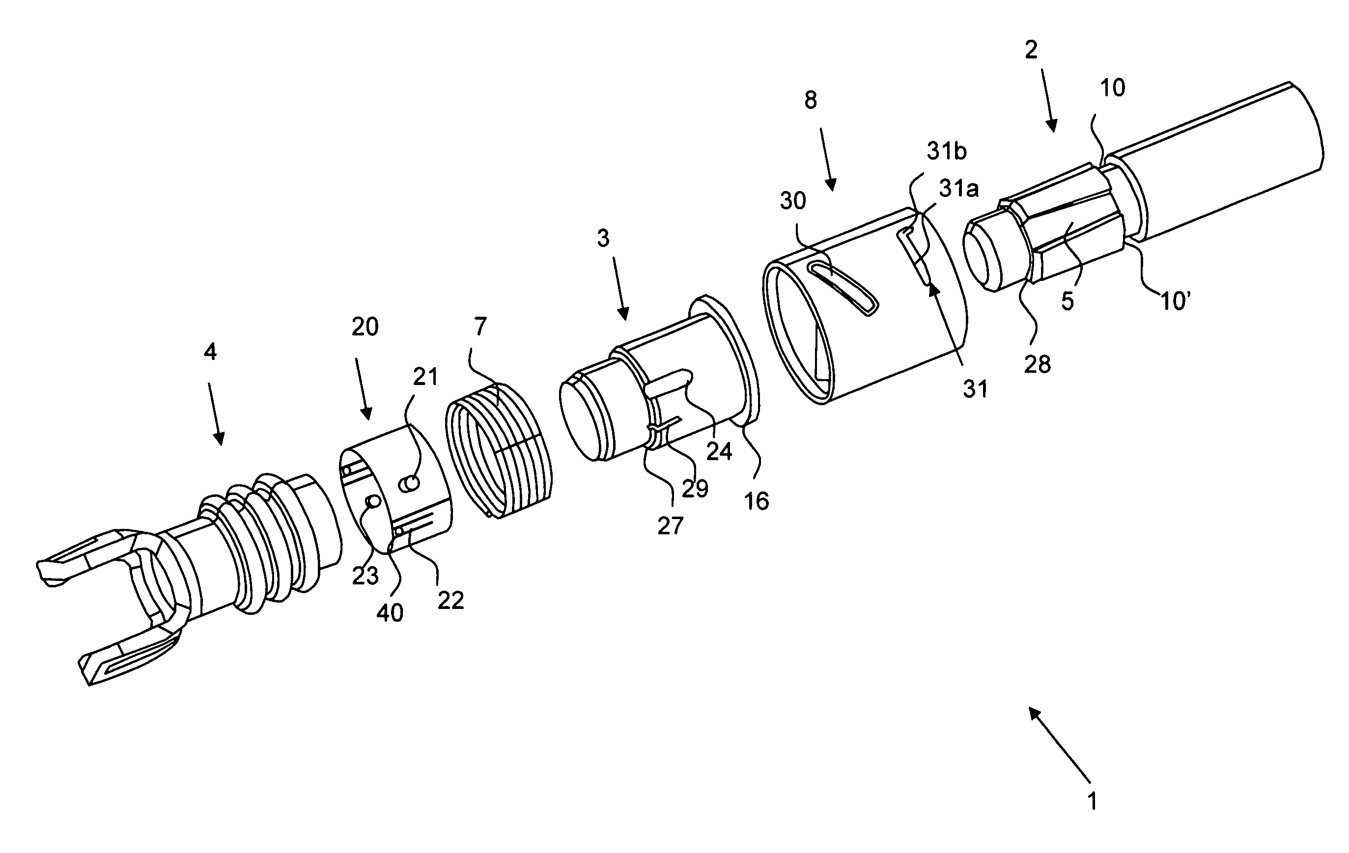
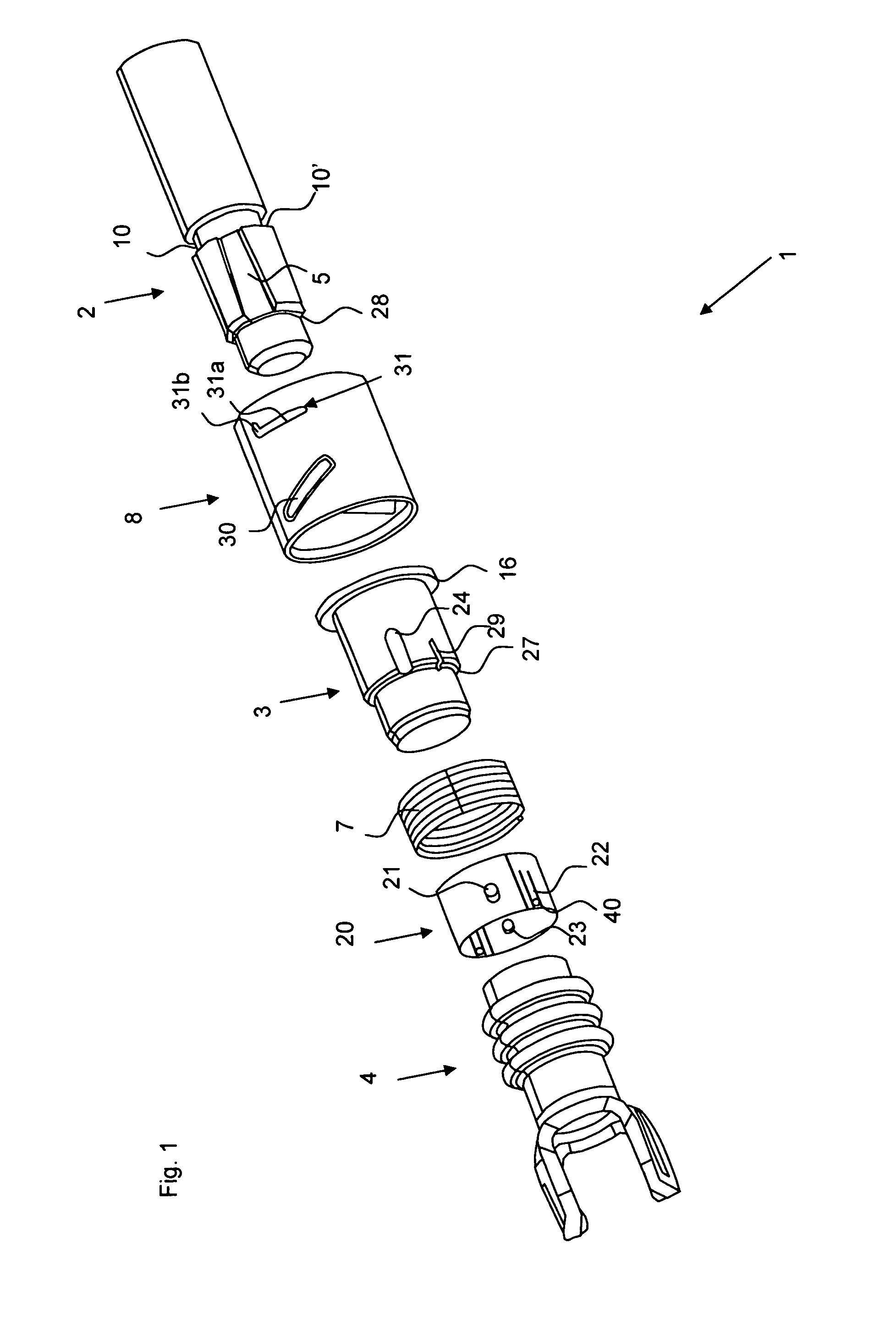
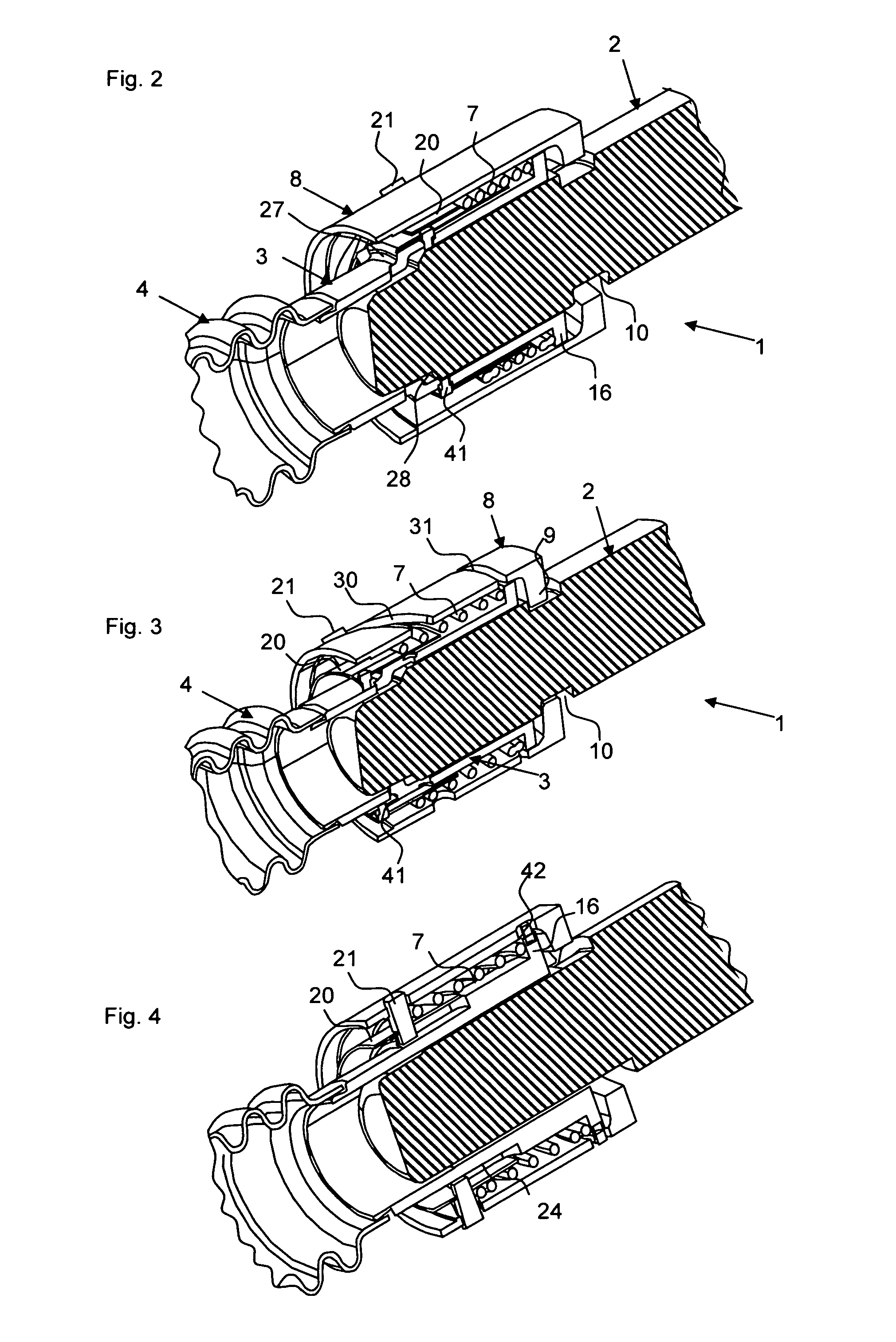
[0037]The invention relates to a steering arrangement having an intermediate piece connecting the steering coupling to the end of the steering spindle. The intermediate piece is, on the one side, hinged on the coupling by means of a fork, while on the other side the intermediate piece is connected to the spindle end. The intermediate piece can, at this interface at which it is connected to the steering spindle end, be swivelled out in the released, i.e. unconnected, state, in order to simplify the assembly of the engine module, which would otherwise be hindered by the steering train due to very little installation space. The steering spindle can be pushed back to some extent in the direction of the steering wheel for assembling the engine module on the body. After the assembly of the engine, the intermediate piece is reconnected to the end of the steering spindle. Since the construction space hardly leaves any space for a manual operation and the connecting partners are difficult to...


PUM


Abstract

A steering spindle has a steering spindle connection connected to a fork crown of a steering coupling via an intermediate piece. The steering spindle connection and the intermediate piece are formed as plug partners at ends facing each other, by means of at least one tongue and groove guide element pair, which provides a torque-transmitting priority control. A groove and a tongue of the at least one tongue and groove guide element pair are positioned in the longitudinal axial direction on the steering spindle connection and the intermediate piece. The steering arrangement includes a clamping device that clamps the plug partners to each other in a plugging position.

Description

BACKGROUND AND SUMMARY OF THE INVENTION[0001]Exemplary embodiments of the invention relate to a steering spindle arrangement of a motor vehicle on the interface of the steering spindle with the steering coupling.[0002]Currently direct screwing of the bottom of the steering spindle with the steering coupling is only possible in the combined field of exhaust gas assemblies, catalytic converters, engines and transmission lines with considerable effort. Here, the steering spindle is screwed in at the bottom with the steering coupling transverse to the steering spindle direction. On the one hand, this has the disadvantage of poor accessibility, and on the other hand the number of variants for optimizing the accessibility for different engine types and steering assemblies, for example left-hand and right-hand drive steering models, is increased, and, in addition, standard assembly sequences, such as the time of assembling the exhaust gas assembly, are hardly or not at all adhered to. In a...

Claims


Application Information

Patent Timeline
Patent Type & Authority Patents(United States)
IPC IPC(8): B62D1/16F16D3/38F16D1/08B62D1/20B62D7/06
CPCB62D7/06B62D1/20F16D1/0876F16D1/0882F16D1/0888F16D3/387
Inventor HEBENSTREIT, AXELLOEFFLER, HANS-DIETERMEYER, THORSTEN
Owner DAIMLER AG
Why Eureka
Try Eureka