Steering Spindle Arrangement

a technology of steering coupling and spindle, which is applied in the direction of couplings, rod connections, manufacturing tools, etc., can solve the problems of only being able to screw the bottom of the steering spindle with the steering coupling, hardly or not adhering, and being easily touched and/or seen. , to prevent the release of the plug partners during the vehicle operation, the effect of preventing the release of the plug partners

Inactive Publication Date: 2014-07-24
DAIMLER AG
View PDF6 Cites 6 Cited by
  • Summary
  • Abstract
  • Description
  • Claims
  • Application Information

AI Technical Summary

Benefits of technology

[0006]Exemplary embodiments of the present invention are directed not only to simplifying the conflation of steering spindle end and steering coupling, but also to creating an arrangement that enables the conflated steering spindle and steering coupling ends to be connected to each other in the correct relative position.
[0008]Due to the guide elements according to the invention, which can be readily touched and / or seen by an assembler, the steering spindle and the intermediate piece of the coupling may, in an advantageously simpler manner, be combined, wherein they always assume the correct relative position to each other due to the pre-determined guiding. The clamping device connects the plug partners by means of contact pressure force in such a way that undesired release of the plug partners during the vehicle operation is prevented.
[0009]The guide elements formed by groove and tongue extend solely along the steering spindle axle. Therefore, a clamp-free manageability of the plug partners, which is easy for the assembler to embody, is enabled for achieving the plug connection.
[0012]In a preferred embodiment, the plugging partners have three grooves and tongues that are positioned in the longitudinal axial direction with 120° displacement to one another, whereby higher torsional moments can be advantageously transferred by the plug partners in their final plugging position without any damage.
[0014]Furthermore, these protrusions can be formed as gears, wherein they can be moved in a longitudinal groove, in particular in the groove of the steering spindle connection serving as a guide element, whereby the sleeve is axially guided. After the axial groove has passed through, the sleeve can be rotated in the annular groove in the peripheral direction into a rotational position, from which an axial rearward displacement is no longer possible. The projections serving as stops can be provided as a group of three, which are offset from one another by 120° in the peripheral direction, such that a tilted position of the sleeve on the steering spindle connection is prevented.

Problems solved by technology

Existing direct screwing of the bottom of the steering spindle with the steering coupling is only possible in the combined field of exhaust gas assemblies, catalytic converters, engines and transmission lines with considerable effort.
This has the disadvantage of poor accessibility.
Further, this increases the number of variants for optimizing the accessibility for different engine types and steering assemblies, for example left-hand and right-hand drive steering models, and, in addition, standard assembly sequences, such as the time of assembling the exhaust gas assembly, are hardly or not at all adhered to.
In another approach regarding the configuration of the device, the steering coupling part is dispensed with and only the steering spindle at the bottom is used, wherein, however, a start-up of the engine in the Z direction during the final assembly, so the conflation of the pre-assembled engine / transmission and chassis unit, is, disadvantageously, not possible.
Due to the tight construction space conditions, the steering train normally impedes the assembly of the engine module with the body.
This is extremely difficult for the person doing the assembling, since the construction space for a manual operation hardly leaves any clearance and the connection partners are very difficult to detect optically.

Method used


Image

  • Steering Spindle Arrangement
  • Steering Spindle Arrangement
  • Steering Spindle Arrangement

Examples


Embodiment Construction

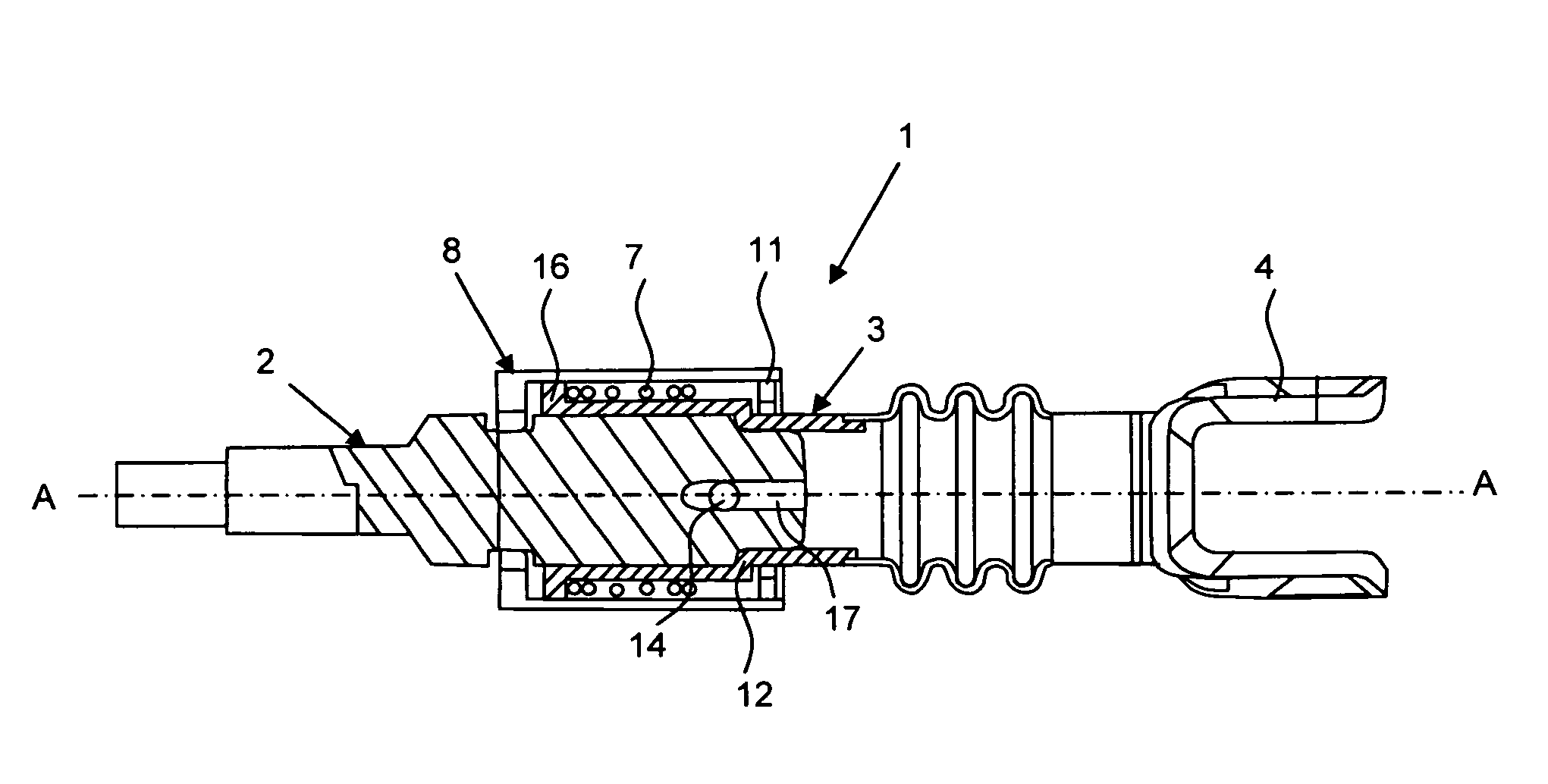
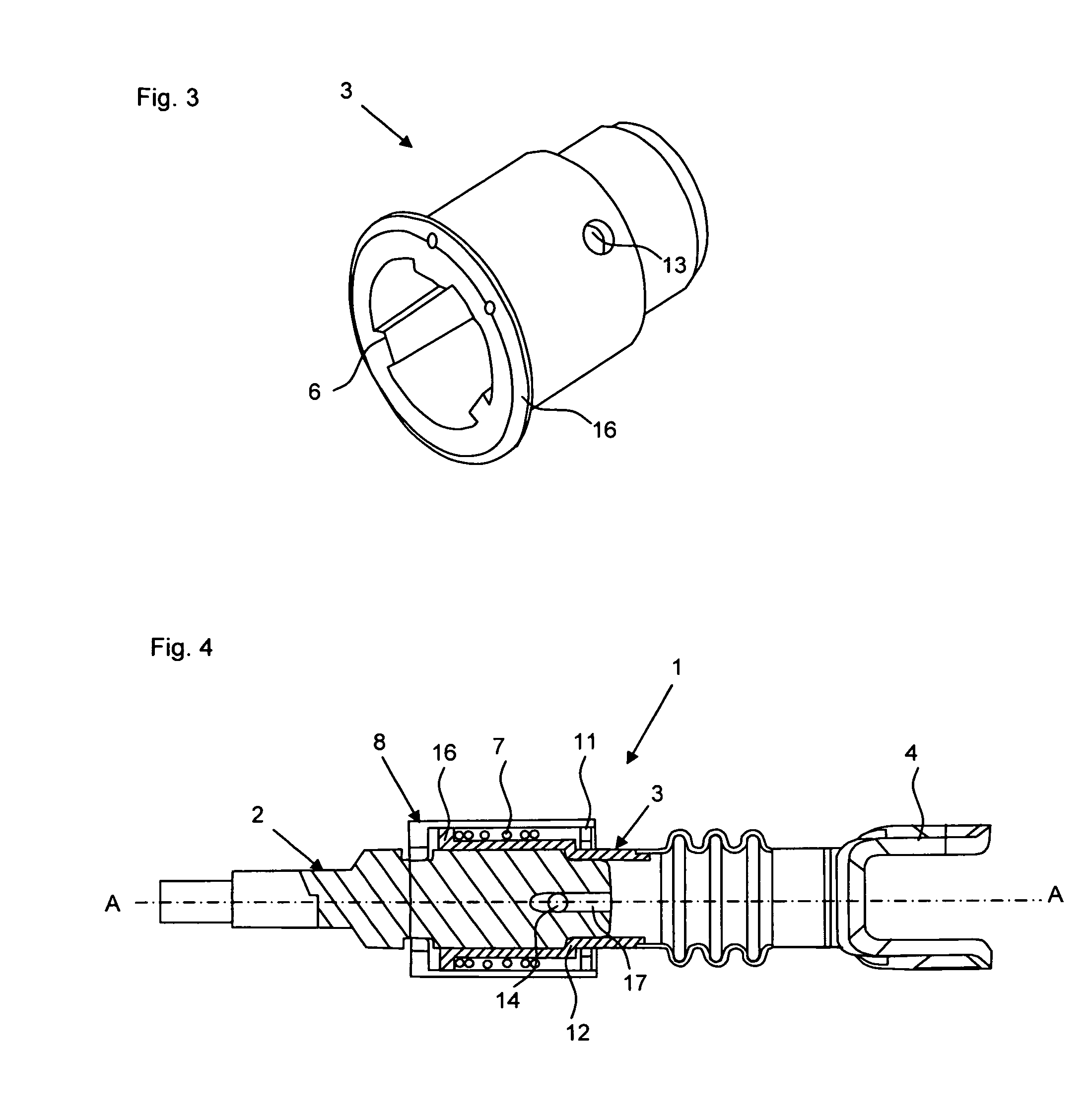
[0029]The device according to the invention relates to a steering arrangement having an intermediate piece in a hub-like design, which connects the fork crown of the steering coupling to the steering spindle connection.

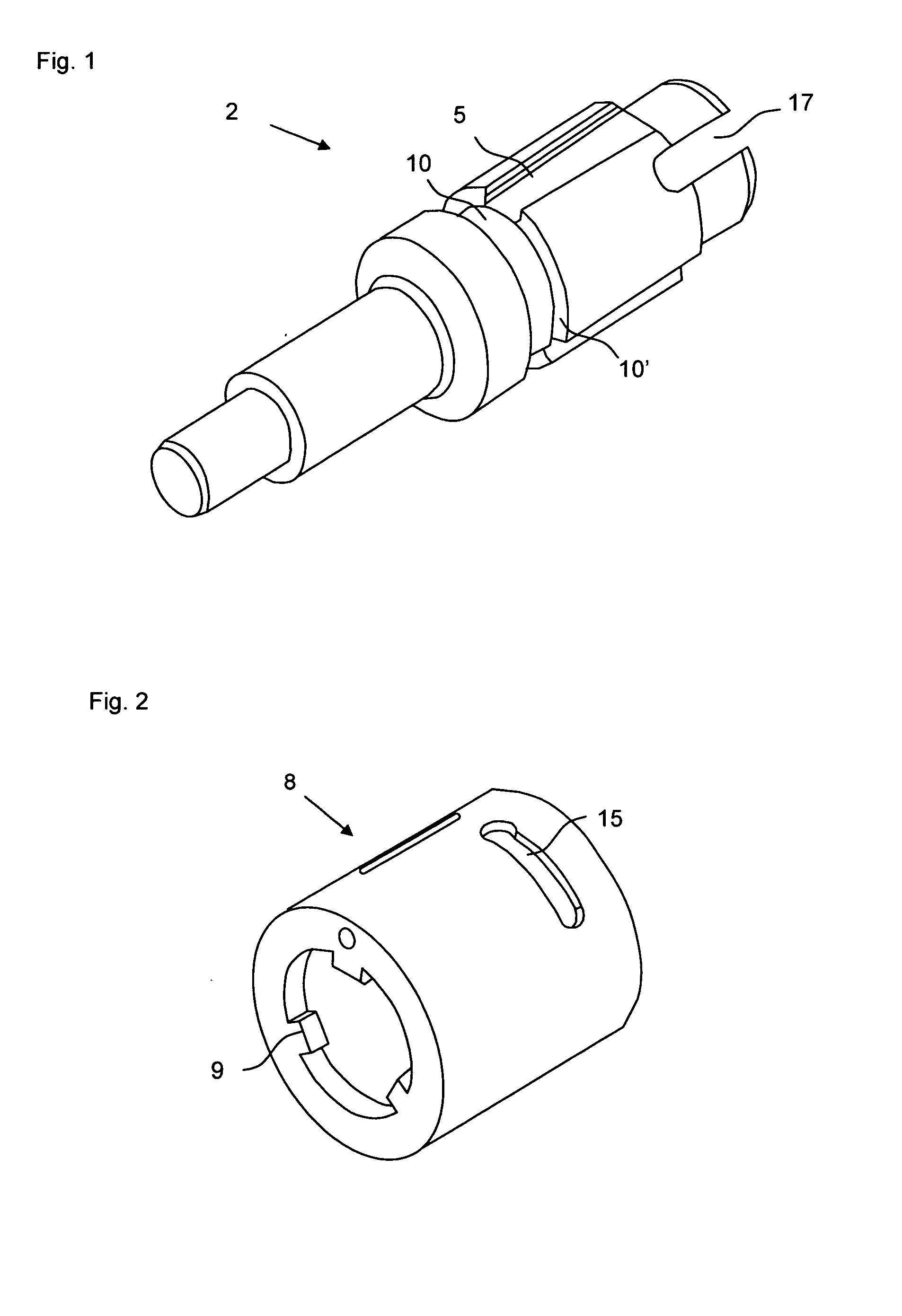
[0030]An embodiment of such a steering arrangement 1 can be seen in FIG. 4. The ends of the intermediate piece 3 and the steering spindle connection 2, which face each other, of the steering spindle are formed as plug partners that have guide elements 5, 6 that interact with each other (cf. FIGS. 1 and 3) and provide a torque-transmitting priority control. The steering arrangement 1 furthermore provides a clamping device, by means of which the plug partners can be clamped together in a plugging position, and which is implemented in FIG. 4 by the helical spring 7, which enables a clearance-free connection.

[0031]Due to the guide elements, which are shown by way of example in FIGS. 1 and 3 as grooves 5 and tongues 6, which can be readily touched and seen by the assembler...


PUM


Abstract

A steering arrangement includes a steering spindle having a steering spindle connection connected to a fork crown of a steering coupling via an intermediate piece. The steering spindle connection and the intermediate piece, which is designed as a hub, are formed as plug partners at ends facing each other, by means of at least one tongue and groove guide element pair positioned in the axial longitudinal direction, which provides a torque-transmitting priority control. Torque-transmitting priority control is achieved by a first guide element arranged on the steering spindle connection, a second guide element of the guide element pair arranged on the intermediate piece, and a clamping device that clamps the plug partners together in a plugging position.

Description

BACKGROUND AND SUMMARY OF THE INVENTION[0001]Exemplary embodiments of the invention relate to a steering spindle arrangement of a motor vehicle on the interface of the steering spindle with the steering coupling.[0002]Existing direct screwing of the bottom of the steering spindle with the steering coupling is only possible in the combined field of exhaust gas assemblies, catalytic converters, engines and transmission lines with considerable effort. Here, the steering spindle is screwed in at the bottom with the steering coupling transverse to the steering spindle direction. This has the disadvantage of poor accessibility. Further, this increases the number of variants for optimizing the accessibility for different engine types and steering assemblies, for example left-hand and right-hand drive steering models, and, in addition, standard assembly sequences, such as the time of assembling the exhaust gas assembly, are hardly or not at all adhered to. In another approach regarding the ...

Claims


Application Information

Patent Timeline
Patent Type & Authority Applications(United States)
IPC IPC(8): F16D1/08B62D1/20
CPCB62D1/20F16D1/08F16D1/0876F16D1/0882F16D1/0888F16D3/387Y10T403/7062Y10T403/7066
Inventor HEBENSTREIT, AXELLOEFFLER, HANS- DIETERMEYER, THORSTEN
Owner DAIMLER AG
Why Eureka
Try Eureka