Steering arrangement

a technology of steering coupling and bottom, applied in the direction of yielding coupling, coupling, connection, etc., can solve the problems of only being able to screw the bottom of the steering spindle with the steering coupling, hardly or not adhering, poor accessibility, etc., and achieve the effect of penetrating dirt and corrosive media into the steering spindl

Active Publication Date: 2015-09-08
DAIMLER AG
View PDF13 Cites 15 Cited by
  • Summary
  • Abstract
  • Description
  • Claims
  • Application Information

AI Technical Summary

Benefits of technology

[0006]Exemplary embodiments of the invention are directed not only to simplifying the conflation of steering spindle end and steering coupling, but an arrangement that enables the conflated steering spindle and steering coupling ends to be connected to each other in the correct relative position and thus for a defective assembly to be prevented.
[0024]In a particularly preferred development, the steering arrangement has a plug that is pressed into the end of the hollow steering spindle and seals it tightly. Penetration of dirt and corrosive media into the steering spindle is hereby prevented. In addition, it serves as protection against noises from the further steering train and the engine bay. When embodied practically, the plug is connected integrally to the orientation pin. The plug can thus consist of an elastomer, plastic or an elastic rubber material.

Problems solved by technology

In existing steering direct screwing of the bottom of the steering spindle with the steering coupling is only possible in the combined field of exhaust gas assemblies, catalytic converters, engines and transmission lines with considerable effort.
This has the disadvantage of poor accessibility, and on the other hand the number of variants for optimizing the accessibility for different engine types and steering assemblies, for example left-hand and right-hand drive steering models, is increased, and, in addition, standard assembly sequences, such as the time of assembling the exhaust gas assembly, are hardly or not at all adhered to.
Due to the poor accessibility, the screwing can only be carried out by the worker in a highly laborious manner, and takes up a large amount of assembly time.
Here, the risk exists that the required screw will slip and be dropped by the worker, whereupon this must then be looked for and found for reasons of production safety.
In this case, the assembly procedure is interrupted, which entails a considerable amount of time.
In another approach, the steering coupling part is dispensed with and only the steering spindle at the bottom is used, wherein, however, a start-up of the engine in the Z direction during the final assembly, and thus the conflation of the pre-assembled engine / transmission and chassis unit, is, disadvantageously, not possible.
Due to the tight construction space conditions, the steering train normally impedes the assembly of the engine module with the body.
This is extremely difficult for the assembler, since the construction space for a manual operation leaves hardly any clearance and the connection partners are very difficult to detect optically.
This was not possible in hitherto existing embodiments, wherein the functionality of the plug connection between tongue and groove was set in separate components.
Then, it is not only guaranteed that the projection of the sleeve has struck behind a tongue of the steering spindle end, but also that the clamping is virtually locked by immersing the pin into the opening, i.e. a release-protected clamping is achieved and undesired disassembly is practically no longer possible.
Due to low clamping effects between the plug partners, this can occur in a particularly cumbersome manner, which takes up the worker's power, patience and time.
The diameter of the pin with its contour elements is smaller than the diameter of the internal width of the shaft, so that the pin can be pushed into the shaft and does not prevent the plug connection of both plug partners.
In the case of mispositioning, an insertion is not possible.
A cumbersome de-threading in the case of defects is no longer present in any way.

Method used


Image

  • Steering arrangement
  • Steering arrangement
  • Steering arrangement

Examples


Embodiment Construction

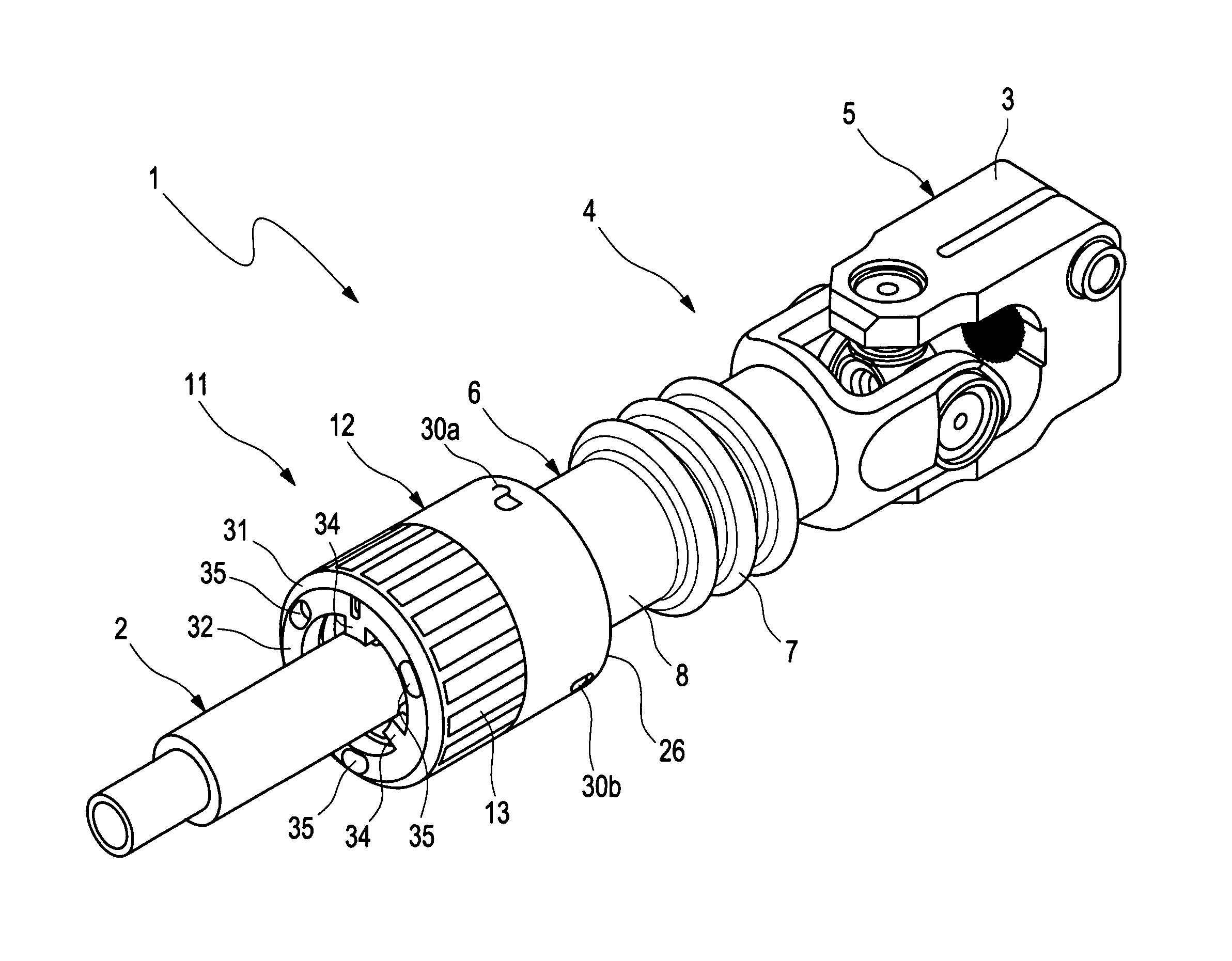
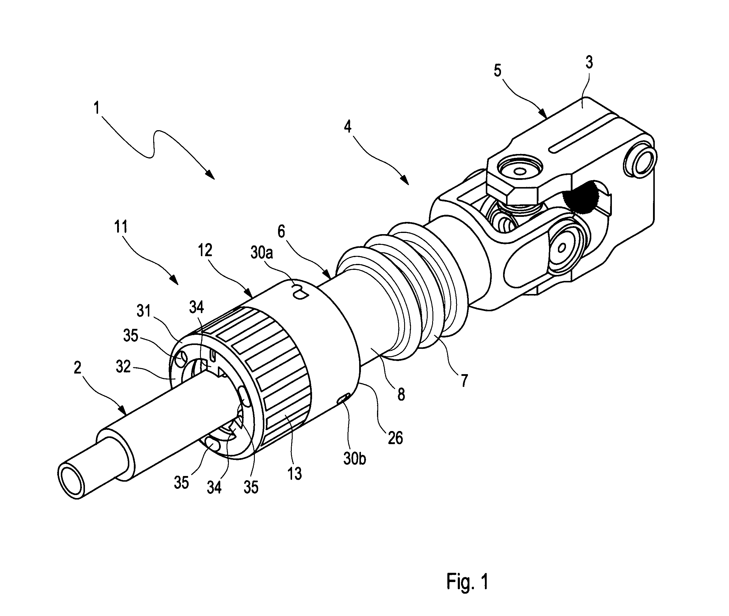
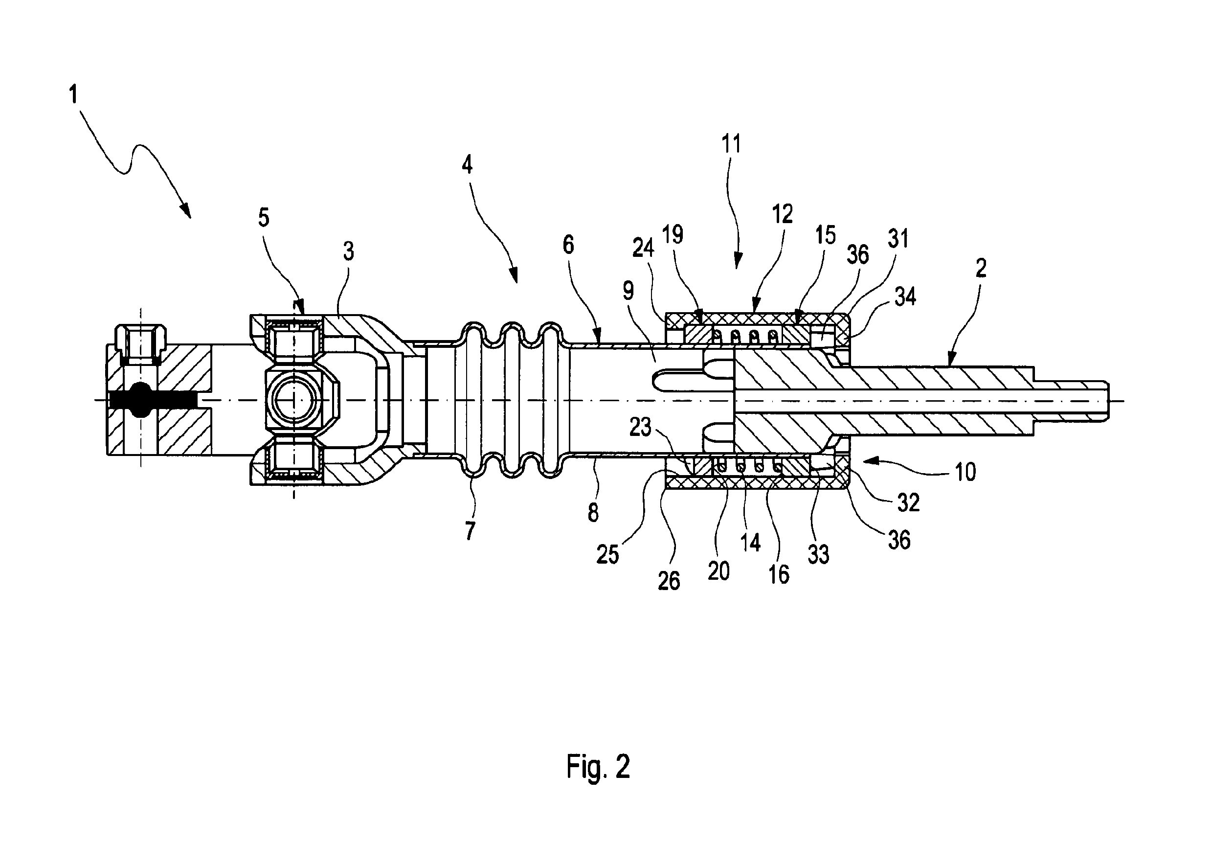
[0034]FIG. 1 depicts an assembled steering arrangement 1 having a steering spindle 2 and a steering coupling 4 provided with a fork crown 3. The fork crown 3 is a component of a universal joint 5 connecting the steering arrangement 1 to a steering gear. A hollow shaft 6 is connected to the fork crown 3 on the other side, which is connected to the fork crown 3 by means of laser welding and which has a corrugated tube section 7. Subsequently, an elongated, cylindrical section 8 of the shaft 6 is connected to the corrugated tube section 7. The shaft 6 can be a casting or a reshaped hollow profile, yet one that is preferably metallic.

[0035]The cylindrical section 8 of the shaft 6 bears a connecting element 9, by means of which an end 10 of the steering spindle 2 is connected to the steering coupling 4 in the form of a plug connection. The shaft 6 furthermore bears a clamping device 11, which, among other things, contains a locating sleeve 12, which coaxially encloses the shaft 6 and is ...


PUM


Abstract

A steering arrangement includes a steering spindle and a steering coupling provided with a fork crown bearing a connecting element that connects an end of the steering spindle to the steering coupling in the form of a plug connection. To enable the combined steering spindle and steering coupling ends to be connected to each other in the correct relative position and thus to be able to prevent a defective assembly, the steering spindle end and the connecting element are coaxial plug partners on ends facing each other, by means of at least one tongue and groove guide element pair that provides a torque-transmitting priority control. The at least one groove and / or the at least one tongue of the guide element pair is molded on the interior of the shaft. A clamping device clamps the plug partners against each other in a plugging position so that they cannot come loose.

Description

BACKGROUND AND SUMMARY OF THE INVENTION[0001]Exemplary embodiments of the present invention relate to a steering arrangement.[0002]In existing steering direct screwing of the bottom of the steering spindle with the steering coupling is only possible in the combined field of exhaust gas assemblies, catalytic converters, engines and transmission lines with considerable effort. Here, the steering spindle is screwed in at the bottom with the steering coupling transverse to the steering spindle direction. This has the disadvantage of poor accessibility, and on the other hand the number of variants for optimizing the accessibility for different engine types and steering assemblies, for example left-hand and right-hand drive steering models, is increased, and, in addition, standard assembly sequences, such as the time of assembling the exhaust gas assembly, are hardly or not at all adhered to. Due to the poor accessibility, the screwing can only be carried out by the worker in a highly lab...

Claims


Application Information

Patent Timeline
Patent Type & Authority Patents(United States)
IPC IPC(8): B62D1/16F16D1/08B62D1/20F16D3/38F16D1/06
CPCB62D1/16B62D1/20F16D1/06F16D1/0876F16D1/0882F16D1/0888F16D3/387Y10T403/7026
Inventor HEBENSTREIT, AXELLOEFFLER, HANS-DIETERMEYER, THORSTEN
Owner DAIMLER AG
Why Eureka
Try Eureka