
Communication device and antenna thereof

a communication device and antenna technology, applied in the direction of antennas, antenna details, electrical devices, etc., can solve the problem that the slot may obviously ruin the appearance of the metal case, and achieve the effect of improving the signal transmitting and receiving capability of the antenna

Active Publication Date: 2015-12-01
KING SLIDE TECH
View PDF11 Cites 15 Cited by
  • Summary
  • Abstract
  • Description
  • Claims
  • Application Information

AI Technical Summary

Benefits of technology

The invention is a device that uses an antenna to improve the way it sends and receives signals. This helps to make the device better at transmitting and receiving information.

Problems solved by technology

But the slot may obviously ruin appearance of the metal case, and the slot needs to be arranged at a position corresponding to a specific area of the metal case.

Method used


Image

  • Communication device and antenna thereof
  • Communication device and antenna thereof
  • Communication device and antenna thereof

Examples


Embodiment Construction

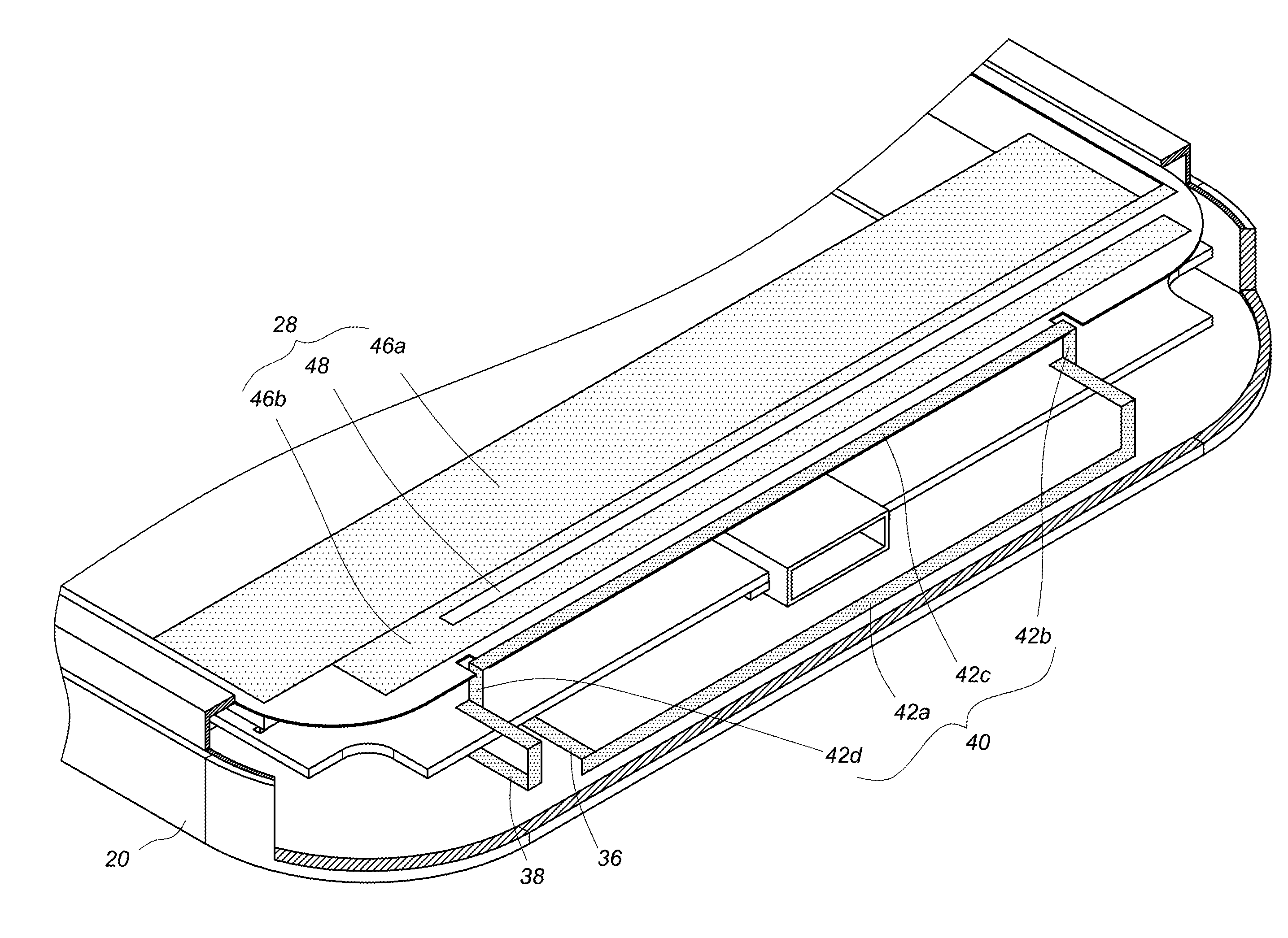
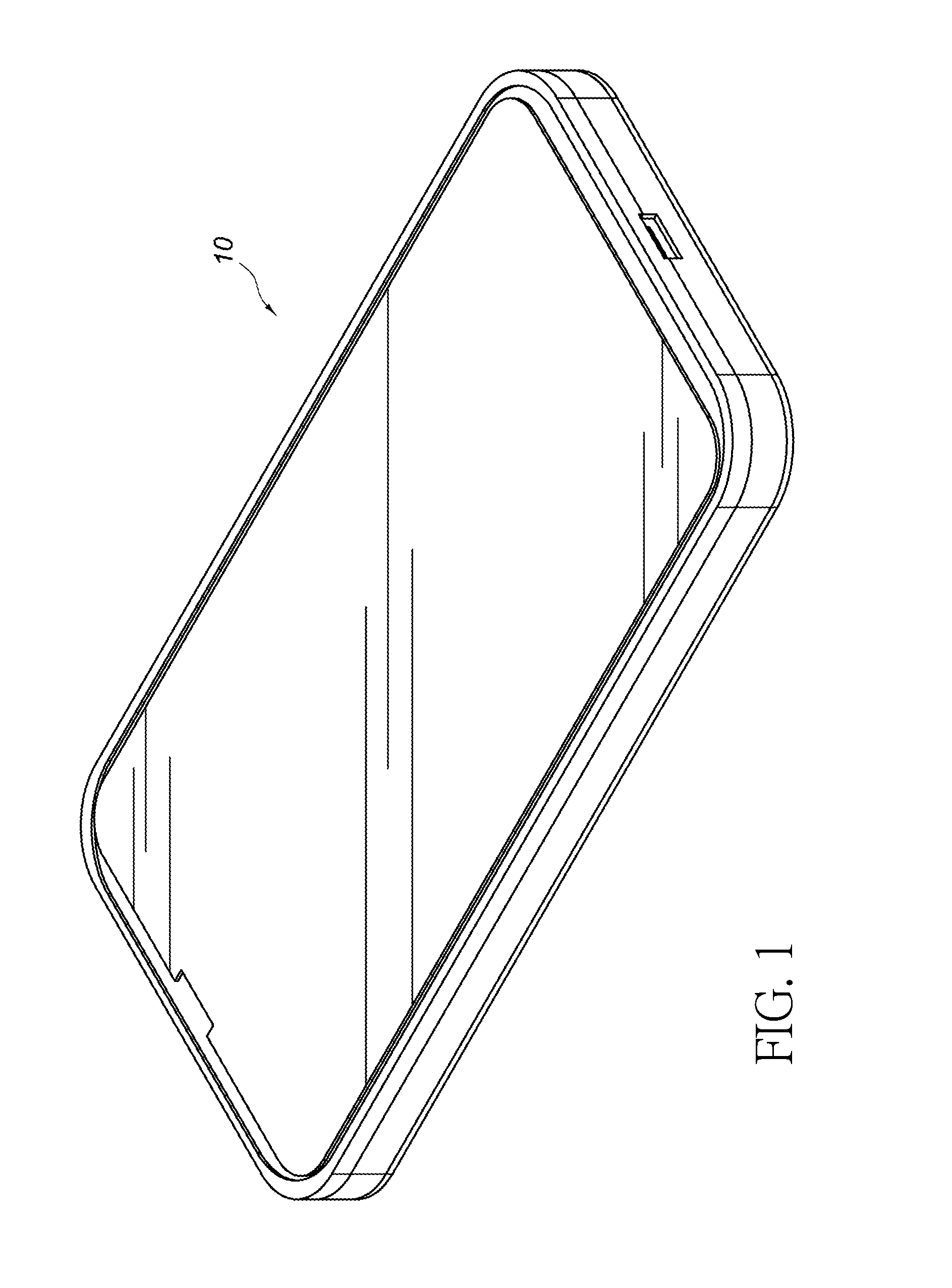
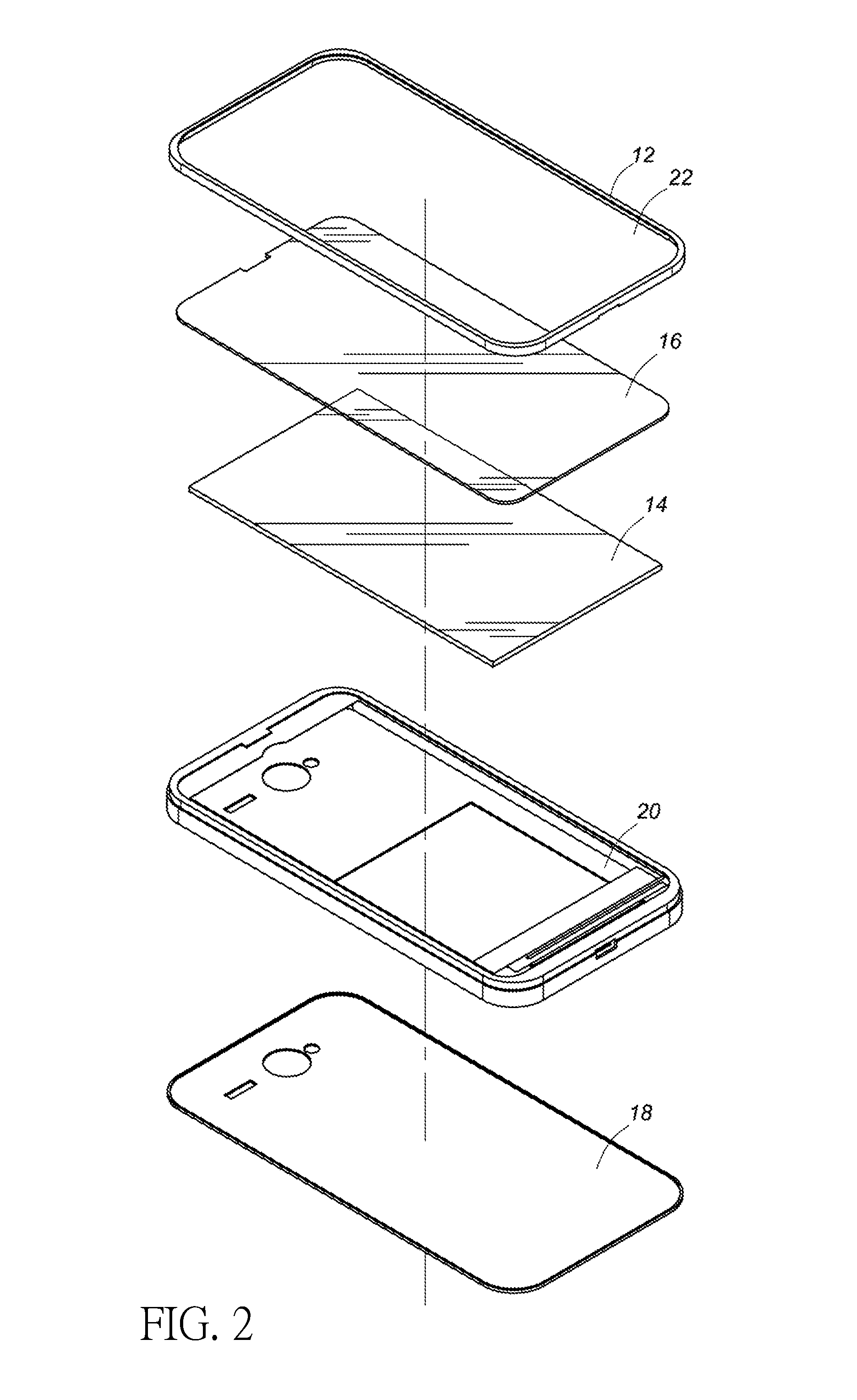
[0023]FIG. 1 and FIG. 2 are diagrams showing a communication device according to an embodiment of the present invention. The communication device 10 comprises a front housing 12, a display module 14, a display panel 16, a back cover 18 and a main body 20. The front housing 12 substantially is a rectangular frame defining a window 22, and the front housing 12 is made of a metal material, but not limited to it. The display panel 16 is installed between the display module 14 and the front housing 12, and corresponds to the window 22 of the front housing 12. The display panel 16 is made of glass, but not limited to it. The back cover is substantially rectangular and located at a position corresponding to the front housing 12. More particularly, the main body 20 is located between the front housing 12 and the back cover 18. In a preferred embodiment, the back cover 18 is made of a metal material, but not limited to it. The back cover 18 can be made of plastic in other embodiment. The bac...


PUM


Abstract

A communication device comprises a front housing, a back cover, a main body, a display panel, a signal feed point, a ground point, an antenna and a conductor. The main body is located between the front housing and the back cover. The antenna is installed on the main body and corresponding to an adjacent edge of the display panel. The antenna comprises a first metal part and a second metal part. The first metal part is coupled to the signal feed point, and the second metal part is coupled to the ground point. A coupling gap is defined between the conductor and the antenna, and at least one part of the conductor corresponds to the display panel.

Description

BACKGROUND OF THE INVENTION[0001]1. Field of the Invention[0002]The present invention relates to an antenna of a communication device, and more particularly, to a metal housing being utilized as an antenna of a communication device, for emitting and receiving radio signals of the communication device.[0003]2. Description of the Prior Art[0004]During product development processes of conventional communication devices, such as mobile communication products, plastic housings are mainly used by manufacturers due to cost concerns, in order to maintain basic radiation characteristics of an antenna. However, a trend of metal housing is currently brought by Apple iPhones and Macbooks. Since the metal housing has light weight, good heat dissipation, high strength, high impact resistance, good looking, anti-electromagnetic and recyclable characteristics, the metal housing is getting more and more popular. Therefore, the metal housings are mainly used in development of new generations of the m...

Claims


Application Information

Patent Timeline
Patent Type & Authority Patents(United States)
IPC IPC(8): H01Q1/24H01Q7/00
CPCH01Q7/00H01Q1/243
Inventor SU, HSIN-CHENGLIU, CHUN-TALIN, SHU-CHEN
Owner KING SLIDE TECH
Learn More