
Increased depth-resolution microscopy

a luminescence microscopy and depth-resolution technology, applied in the field of luminescence microscopy, can solve the problems of only achieving localization accuracy laterally, limiting the method to a two-dimensional sample analysis, and distortion of the image of the luminescent marking molecule, etc., and achieve good high resolution

Active Publication Date: 2015-12-01
CARL ZEISS MICROSCOPY GMBH
View PDF26 Cites 32 Cited by
  • Summary
  • Abstract
  • Description
  • Claims
  • Application Information

AI Technical Summary

Benefits of technology

The patent text states that using a two-photon process for excitation and activation can provide a sharp intensity distribution in the depth direction, resulting in high-resolution imaging.

Problems solved by technology

However, this localization accuracy is achieved only laterally, i.e. in a plane assigned to the image plane of the camera.
In this respect, the methods are thus limited to a two-dimensional sample analysis.
A disadvantage of this method is that the local environment and the orientation of a molecular dipole can also result in a distortion of the image of the luminescent marking molecule that has nothing to do with the depth position.
This method requires two high-sensitivity cameras, or two images have to be arranged next to each other on the receiving region of a high-sensitivity camera, which naturally results in a limitation of the image field.

Method used


Image

  • Increased depth-resolution microscopy
  • Increased depth-resolution microscopy
  • Increased depth-resolution microscopy

Examples


Embodiment Construction

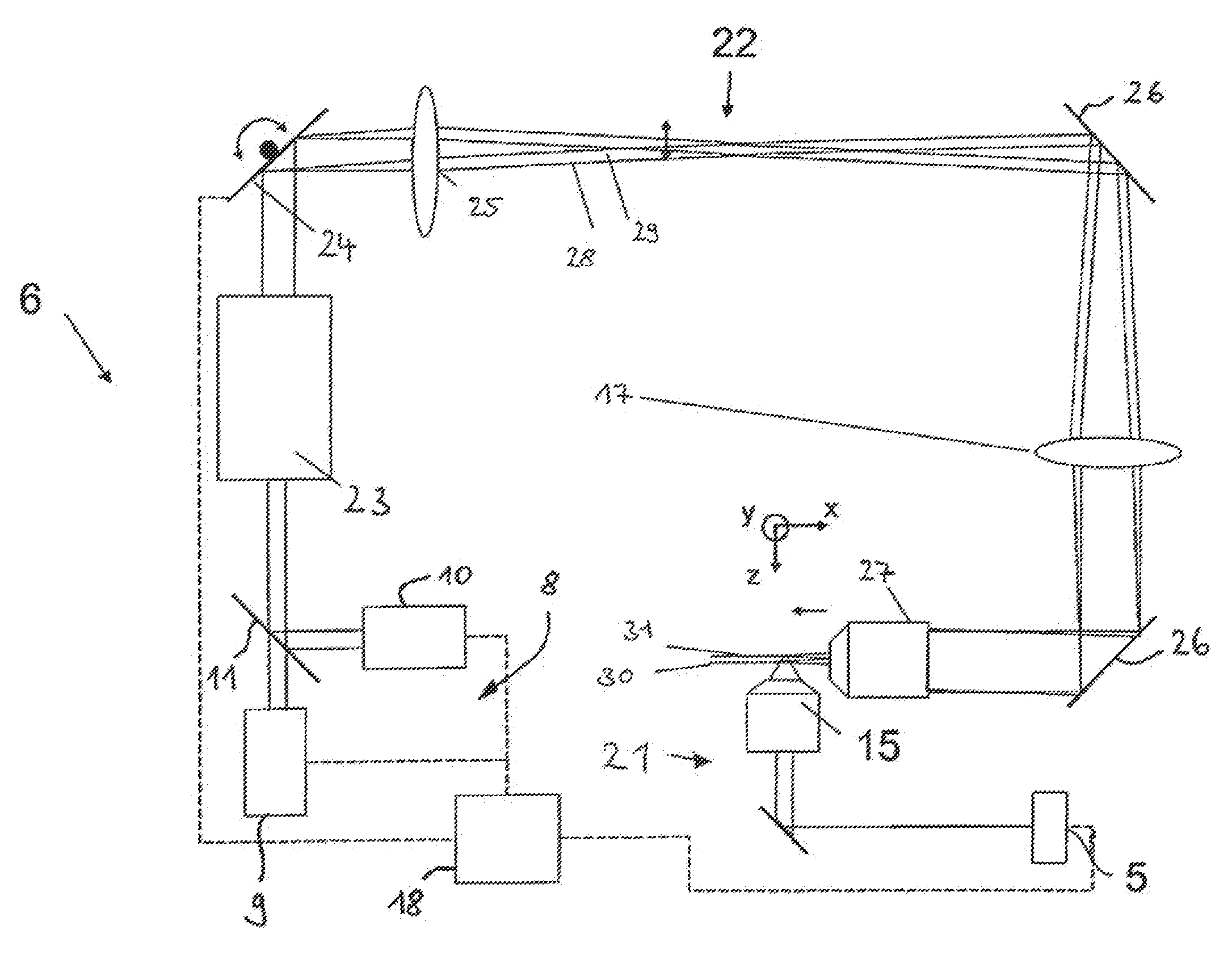
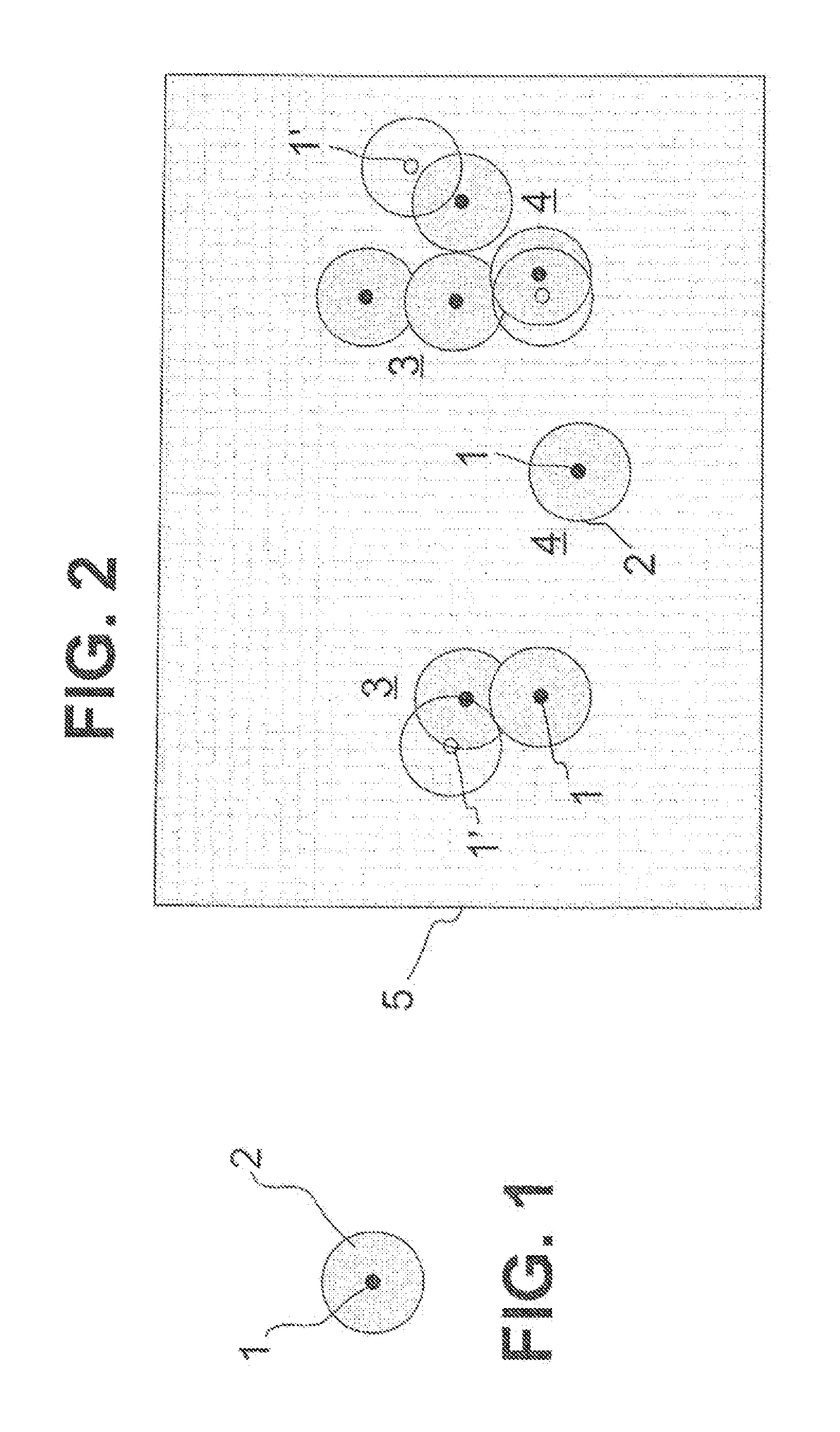
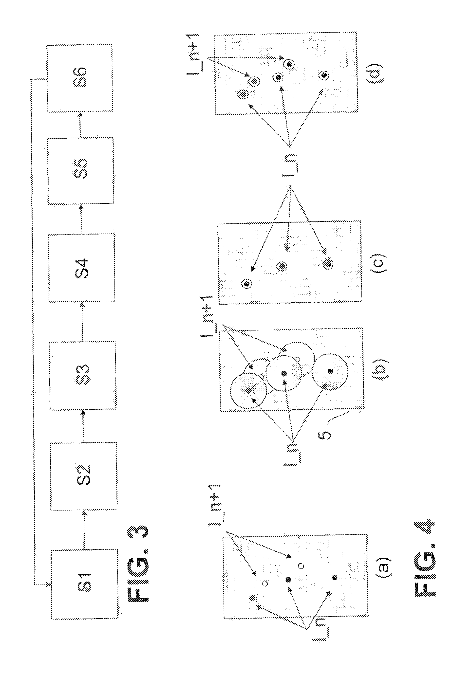
[0047]Shown schematically in FIG. 1 is a marking molecule 1 that has been excited to fluorescence. Naturally, fluorescence detection requires a large number of excitations, since each excitation delivers exactly one fluorescence photon, and the detection of radiation requires integration of many fluorescence photons. On the basis of physical principles, the fluorescent radiation emitted by the marking molecule 1 can be detected only with a limited optical resolution in a microscope. Even if the microscope achieves the diffraction limit of the optical resolution, the photons of the fluorescent marking molecule 1 are still scattered because of diffraction, and are therefore detected in a diffraction disc 2. Thus, in principle, instead of representing the geometrical extent of the marking molecule 1, which in FIG. 1 is indicated schematically as a black circle, the microscope represents a larger object, which in FIG. 1 is illustrated by the diffraction disc 2. The size of the diffracti...


PUM

PropertyMeasurementUnit
wavelengthaaaaaaaaaa

Abstract

A method for high-resolution luminescence microscopy of a sample marked with marking molecules that can be activated to excite particular luminescent radiation, including: repeated activation of a subset of the marking molecules to emit luminescent radiation; repeated imaging of the sample along a depth direction and with a predetermined optical resolution; and producing images from the repeated imaging. Locations of the marking molecules are determined with a spatial resolution that is increased above the predetermined optical resolution. Activation of the marking molecules can be through radiation introduced into multiple regions, each extending along a plane substantially perpendicular to the depth direction. The regions can be arranged so that the regions are behind one another and overlap only partially. Separate images of the sample may be recorded for activation in each of the regions in order to obtain depth information relating to the marking molecules from the separate images.

Description

RELATED APPLICATIONS[0001]The present application is a National Phase entry of PCT Application No. PCT / EP2011 / 069918, filed Nov. 11, 2011, which claims priority from DE Patent Application No. 10 2010 044 013.2, filed Nov. 16, 2010, which applications are hereby incorporated by reference in their entireties.FIELD OF THE INVENTION[0002]The invention relates to a method for high-resolution luminescence microscopy of a sample, which is marked with marking molecules which can be activated in such a manner that, once activated, they can be excited to emit particular luminescent radiation, wherein the method has the following steps:[0003]a) repeated activation and excitation of a subset of the marking molecules present in the sample to emit luminescent radiation, wherein, in the sample, at least some of the luminescent marking molecules are at least at a distance from the luminescent marking molecules immediately adjacent thereto, which distance is greater than or equal to a length which r...

Claims


Application Information

Patent Timeline
Patent Type & Authority Patents(United States)
IPC IPC(8): G01N21/64G02B21/36G02B21/16G02B21/00G02B27/58
CPCG01N21/6447G01N21/6428G01N21/6458G02B21/16G02B21/367G02B27/58G02B21/0076G01N21/64
Inventor KALKBRENNER, THOMASLIPPERT, HELMUTKLEPPE, INGO
Owner CARL ZEISS MICROSCOPY GMBH
Learn More