
Surgical apparatus with removable tool cartridge

a technology of surgical instruments and tool cartridges, applied in the field of electrosurgical instruments, can solve the problems of increasing the cost of surgical procedures, affecting the patient's final payment,

Active Publication Date: 2015-12-01
BOVIE MEDICAL CORP
View PDF30 Cites 142 Cited by
  • Summary
  • Abstract
  • Description
  • Claims
  • Application Information

AI Technical Summary

Benefits of technology

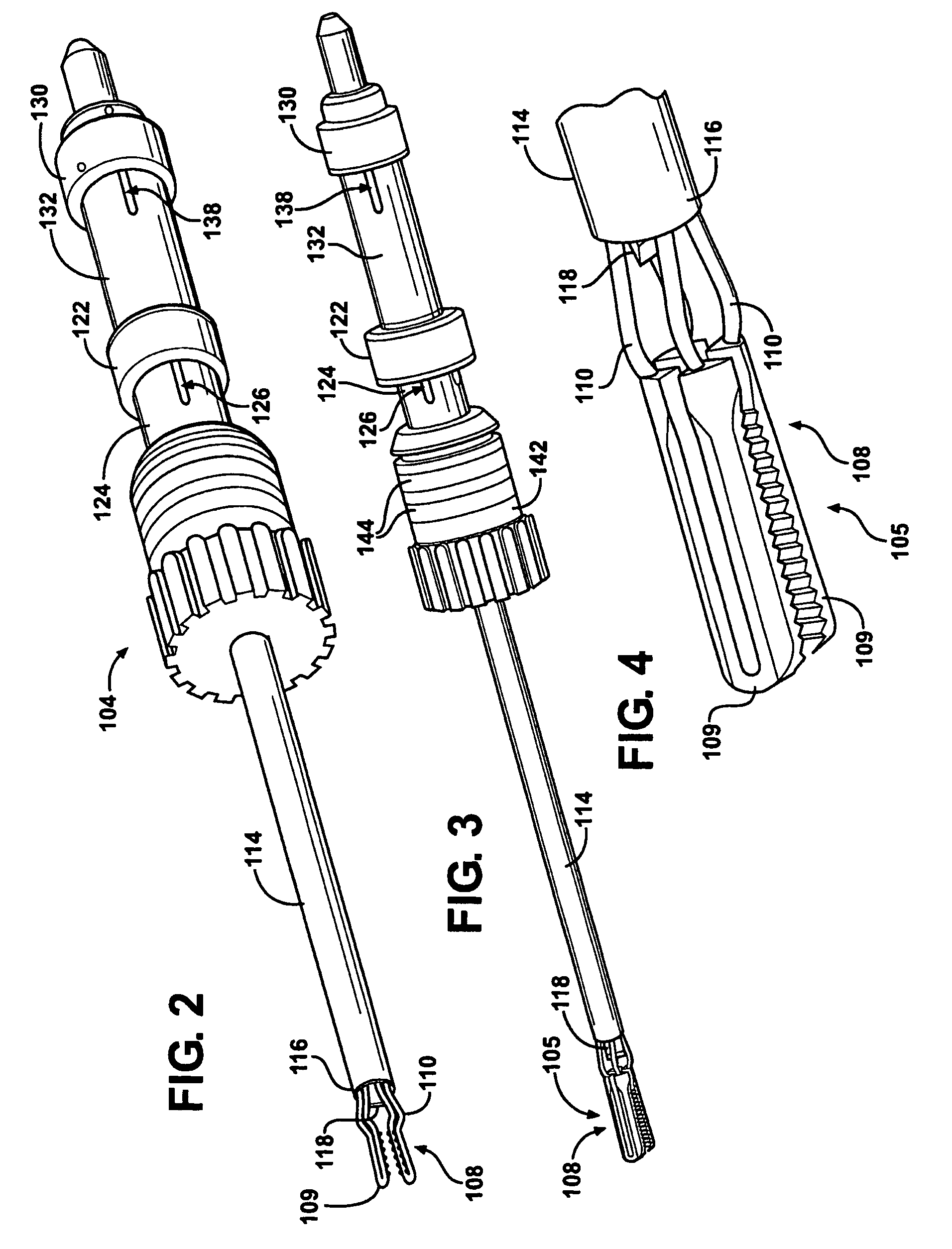
[0011]The surgical apparatus of the subject invention provides numerous advantages over the prior art. The use of sheaths enclosing the transmission helps protect these components from dirt or damage, allowing positioning of springs and pistons thus executing desired movements. Likewise, the gate mechanism also protects the interior of the handle assembly from debris and damage. Moreover, the apparatus allows for automatic switching between coagulation and cutting modes. This automatic switching allows the surgeon to concentrate on the surgical procedure, instead of worrying about turning dials on a power supply.

Problems solved by technology

Because of this one-piece construction, these instruments tend to be expensive.
Furthermore, due to the risk of infections, these instruments need to be sterilized and replaced often.
Obviously, routinely replacing these expensive instruments drives up the cost of surgical procedures which must ultimately be borne by the patient.

Method used


Image

  • Surgical apparatus with removable tool cartridge
  • Surgical apparatus with removable tool cartridge
  • Surgical apparatus with removable tool cartridge

Examples


third embodiment

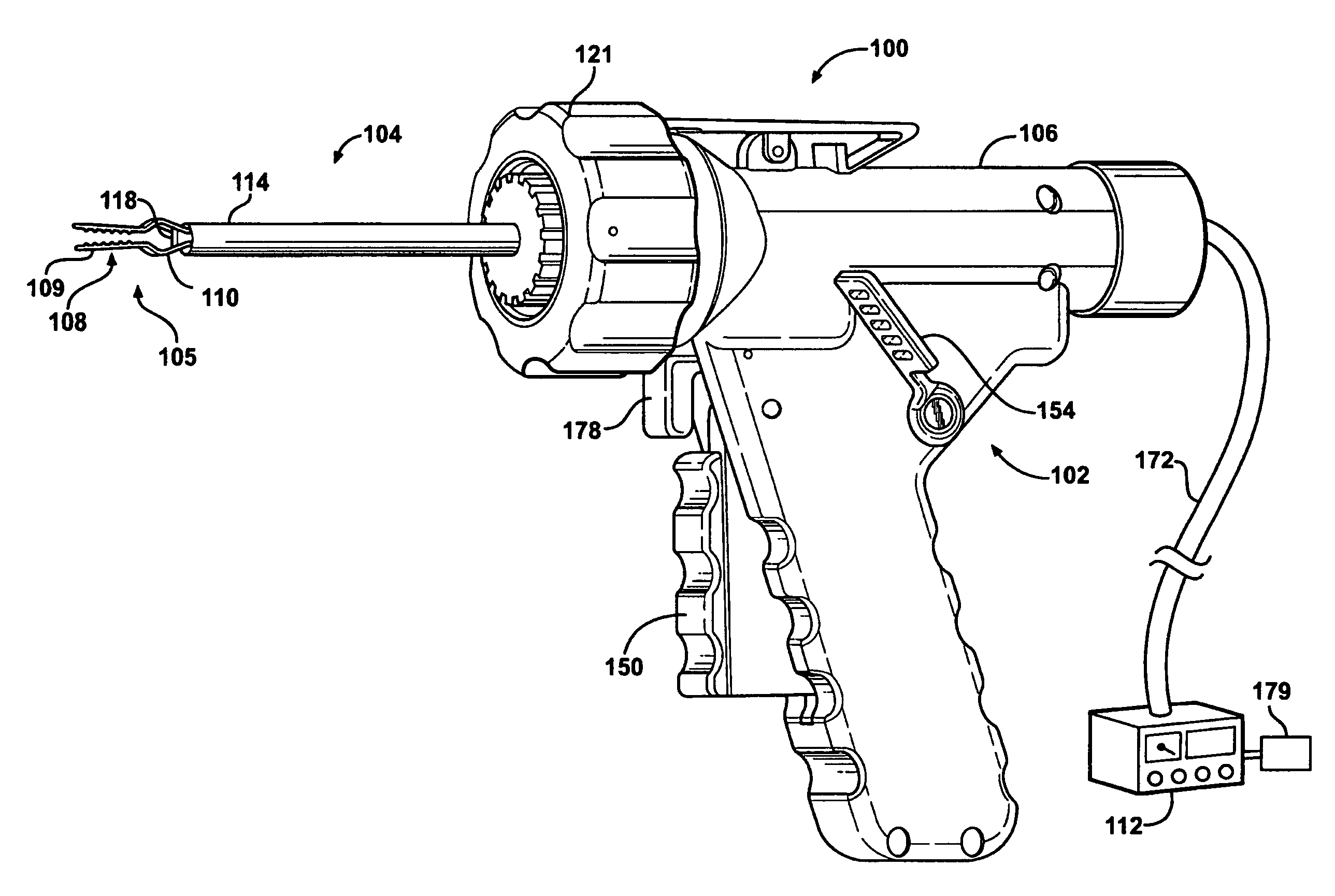
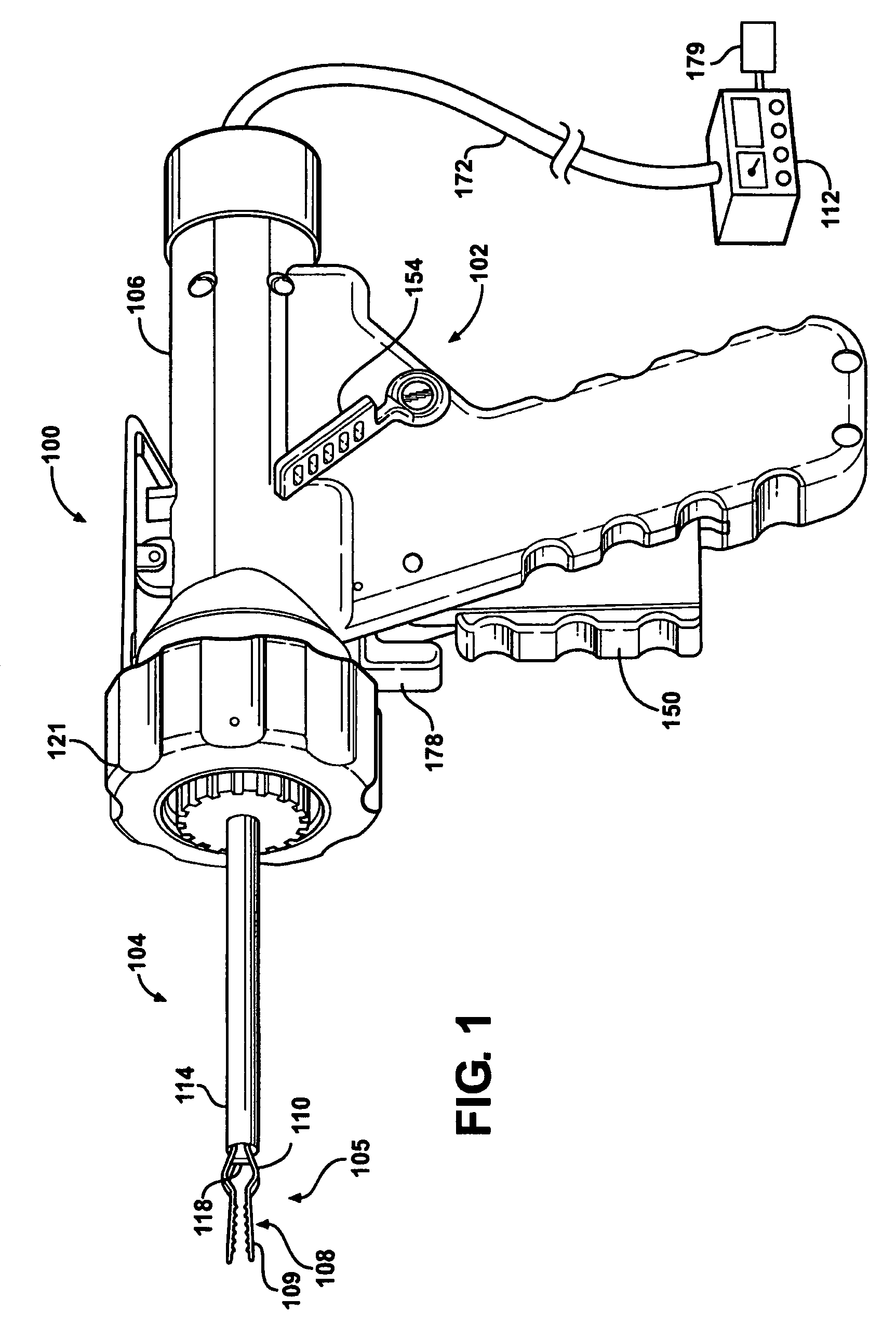
[0063]The first tool actuation lever 150 is positioned both inside and outside of the housing 106 such that a user of the apparatus 100 may actuate the first tool actuation lever 150. Preferably, the first tool actuation lever 150 includes a first forked part 152 extending thereof. The first forked part 152 contacts the first grip 122. the handle assembly 102 includes an auxiliary forked part 153 operatively connected to the first tool actuation lever 150, as shown in FIGS. 25 and 26. The auxiliary forked part 153 may actuate other grips (not numbered) on the tool assembly 104.

[0064]The handle assembly 102 also includes a second tool actuation lever 154. The second tool actuation lever 154 is preferably pivotably hinged to allow motion about a pin 156. In the illustrated embodiments, the second tool actuation lever 154 is operatively connected to the second grip 130 of the tool cartridge 104. Accordingly, depression of the second tool actuation lever 154 moves the second grip 130 an...

second embodiment

[0079]The handle assembly 102 may also include a lever locking assembly 182. In the second embodiment, as best shown in FIG. 16, the lever locking assembly 182 is used to retain the first tool actuation lever 150 in position. The lever locking assembly 182 includes a plurality of teeth 186 in a saw-tooth configuration. The teeth 186 interface with a pin 188 extending from the first tool actuation lever 150. As the first tool actuation lever 150 is depressed, the pin 188 latches against one of the teeth 186. This holds the first tool actuation lever 150 (and accordingly the jaws 108) in position such that the surgeon need not retain pressure on the first tool actuation lever 150. The lever locking assembly also includes a tab 184 extending from the teeth 186 and positioned outside of the housing 106 to allow release of the pin 188 from the teeth.

[0080]The handle assembly 102 and / or the tool cartridge 104 may also include an identification chip 194. In the second embodiment, where the...


PUM


Abstract

A surgical apparatus for coagulating and cutting tissue includes a handle assembly and a tool cartridge. The tool cartridge includes electrically conductive movable tools, such as jaws and a blade, for cutting tissue. The jaws and blade each are connected to a transmission to facilitate movement. Multiple sheaths are used to encompass and protect the transmissions. Slidable grips are disposed outside of the sheaths and operatively connected to the transmissions that are disposed within the sheaths. At least one lever is supported by the handle assembly and engagable with the grips to facilitate movement of the grips, and thus, the tools.

Description

CROSS REFERENCE TO RELATED APPLICATION[0001]This application claims the benefit of provisional patent application No. 61 / 014,612, filed Dec. 18, 2007, provisional patent application No. 61 / 117,380, filed Nov. 24, 2008, and provisional patent application No. 61 / 119,150, filed Dec. 2, 2008, which are each hereby incorporated by reference.BACKGROUND OF THE INVENTION[0002]1. Field of the Invention[0003]The subject invention relates to surgical instruments. Specifically, the subject invention relates to electrosurgical instruments for cutting tissue such as blood vessels.[0004]2. Description of the Related Art[0005]Electrosurgical instruments have gained high acceptance in the medical community for coagulating and cutting tissue, such as blood vessels. These instruments are typically “one-piece” assemblies where the delicate tools used in the surgery are permanently affixed to handle and trigger mechanisms.[0006]Because of this one-piece construction, these instruments tend to be expensi...

Claims


Application Information

Patent Timeline
Patent Type & Authority Patents(United States)
IPC IPC(8): A61B18/18A61B18/14A61B18/00A61B17/00
CPCA61B18/1445A61B2017/0046A61B2017/00296A61B2017/00464A61B2018/1495A61B2018/00404A61B2018/00601A61B2018/1412A61B2018/1455A61B2018/00178
Inventor LIVNEH, STEVE
Owner BOVIE MEDICAL CORP
Learn More