Image forming apparatus
a technology of image forming apparatus and forming apparatus, which is applied in the direction of electrographic process apparatus, instruments, optics, etc., can solve the problems of reducing the productivity of the image forming apparatus, hindering normal image formation, and inability to form high-quality images, etc., and achieves the effect of lowering productivity
- Summary
- Abstract
- Description
- Claims
- Application Information
AI Technical Summary
Benefits of technology
Problems solved by technology
Method used
Image

Examples
first embodiment
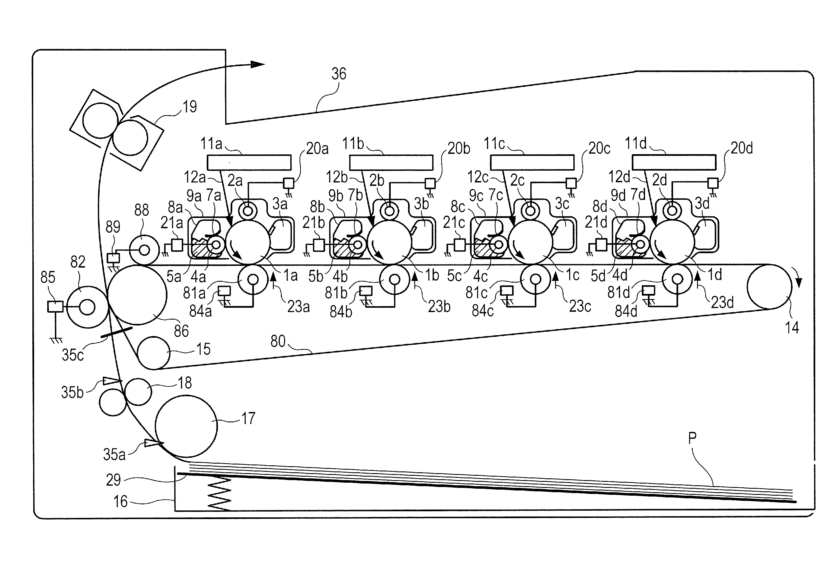
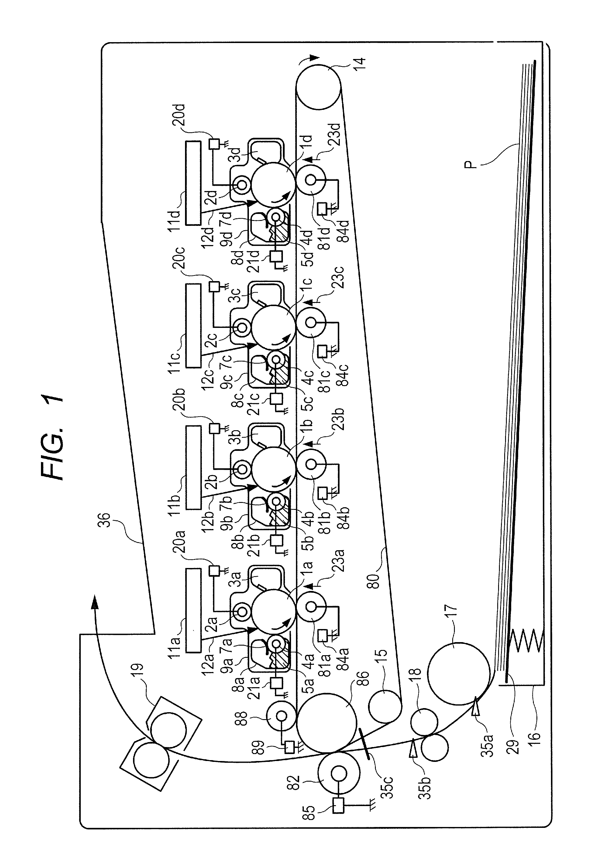
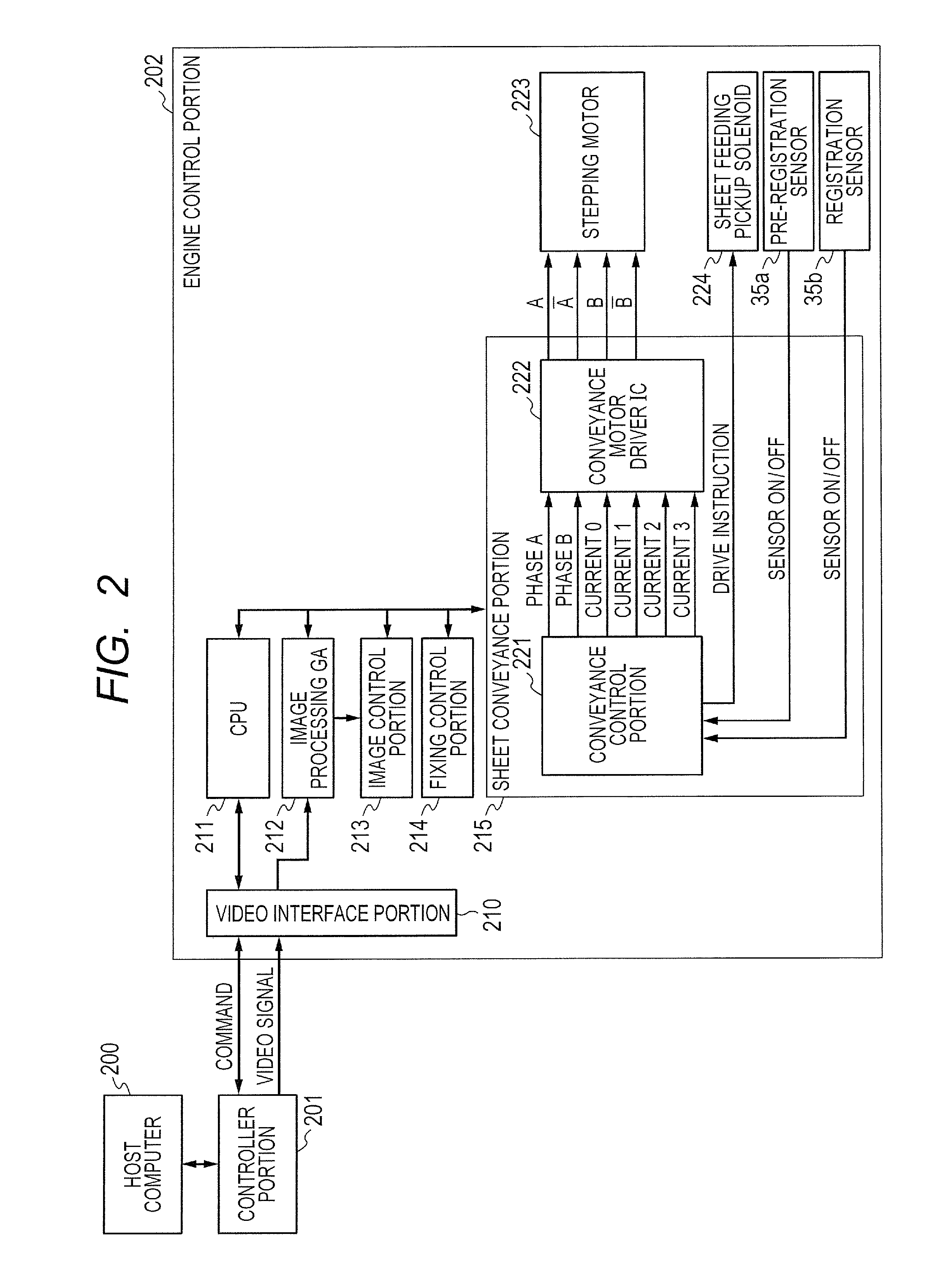
[0026]In a first embodiment of the present invention, a method performed by an image forming apparatus for conveying a sheet from a start of sheet feeding up to an arrival at a secondary transfer position by using one driving source in a case where two sheet detection sensors are provided between a sheet feeding position and the secondary transfer position (transfer position) and printing is continuously performed on two sheets is described as follows. That is, a method of carrying out conveyance speed control for a subsequent sheet based on a result of detecting a position of a preceding sheet being a recording material, which is obtained by the sheet detection sensor (hereinafter referred to as “downstream-side sheet detection sensor”) on a downstream side in a conveying direction of the recording material (hereinafter referred to simply as “downstream side”), is described. The preceding sheet (first recording material) represents, when a given recording material is being conveyed...
second embodiment
[0104]In the first embodiment, the conveyance speed control A is performed after the preceding sheet has passed through the registration roller 18, and hence the conveyance speed control A is carried out after waiting until the trailing edge of the preceding sheet has passed through the registration sensor 35b. However, the registration sensor 35b detects the trailing edge of the recording material at the timing at which the trailing edge of the recording material arrives at the position downstream of the nip portion of the registration roller 18. FIG. 6 illustrates a main part of the conveying path between a sheet feeding portion and a secondary transfer portion. As illustrated in FIG. 6, at a timing (600) at which the trailing edge of the recording material (thick solid line indicated as “sheet” in the figure) passes through the registration sensor 35b, the trailing edge of the recording material has been conveyed downstream of the nip portion of the registration roller 18 by a di...
third embodiment
[0127]In a third embodiment of the present invention, which has a structure in which a distance between the position of the pre-registration sensor 35a and the position of the registration sensor 35b is shorter than the image interval of the continuous printing, a method of carrying out the conveyance speed control on an acceleration side from the pre-registration sensor 35a and carrying out the conveyance speed control on a deceleration side from the registration sensor 35b is described. According to this embodiment, the conveyance speed control on the acceleration side is carried out from the pre-registration sensor 35a, and hence it is possible to secure more sections that enable correction of the acceleration. On the other hand, the conveyance speed control on the deceleration side is carried out from the registration sensor 35b, and hence it is possible to reduce the conveyance variation between the pre-registration sensor 35a and the registration sensor 35b. An overall structu...
PUM
 Abstract
Description
Claims
Application Information
 - R&D
- Intellectual Property
- Life Sciences
- Materials
- Tech Scout
- Unparalleled Data Quality
- Higher Quality Content
- 60% Fewer Hallucinations
Browse by: Latest US Patents, China's latest patents, Technical Efficacy Thesaurus, Application Domain, Technology Topic, Popular Technical Reports.
© 2025 PatSnap. All rights reserved.Legal|Privacy policy|Modern Slavery Act Transparency Statement|Sitemap|About US| Contact US: help@patsnap.com