Eureka AIR delivers breakthrough ideas for toughest innovation challenges, trusted by R&D personnel around the world.

Simple open-end wrench

a simple, wrench technology, applied in the field of open-end wrenches, can solve the problems of ratchet wrenches that cannot withstand a large torque transmission well, each dog does not have a strong structure, pivots to break, etc., and achieves a smaller minimum swing angle and better withstands torque transmission

Active Publication Date: 2015-11-17
CHILI DEV CO LTD
View PDF31 Cites 0 Cited by
  • Summary
  • Abstract
  • Description
  • Claims
  • Application Information

AI Technical Summary

Benefits of technology

[0010]It is therefore an objective of the present invention to provide a ratchet wrench which better withstands torque transmission and is capable of being operated through a relatively smaller minimum swing angle action.

Problems solved by technology

However, each dog does not have a strong structure, because it is made with a through hole for pivot.
A larger shear force can cause the pivot to break, because the pivot is limited to have a relatively small cross-sectional area.
Therefore, the ratchet wrench can't withstand a large torque transmission well.

Method used


Image

  • Simple open-end wrench
  • Simple open-end wrench
  • Simple open-end wrench

Examples


Embodiment Construction

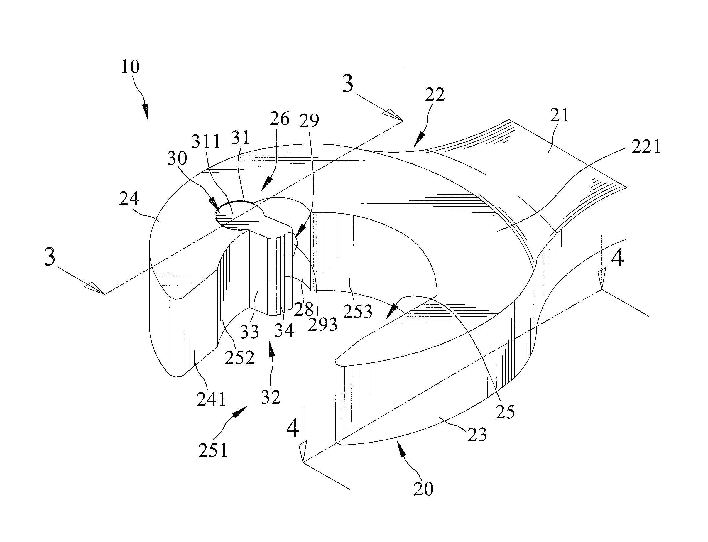
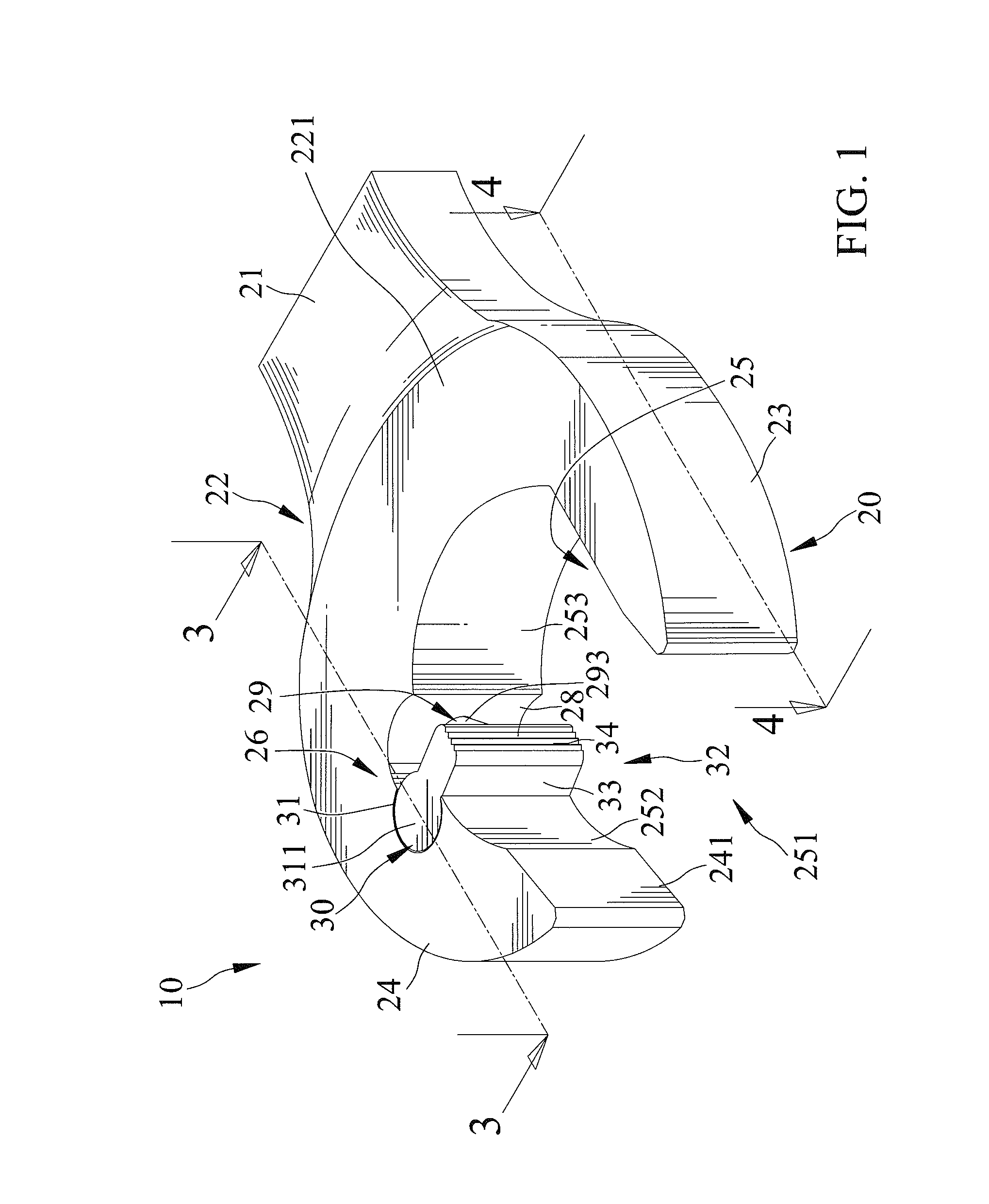
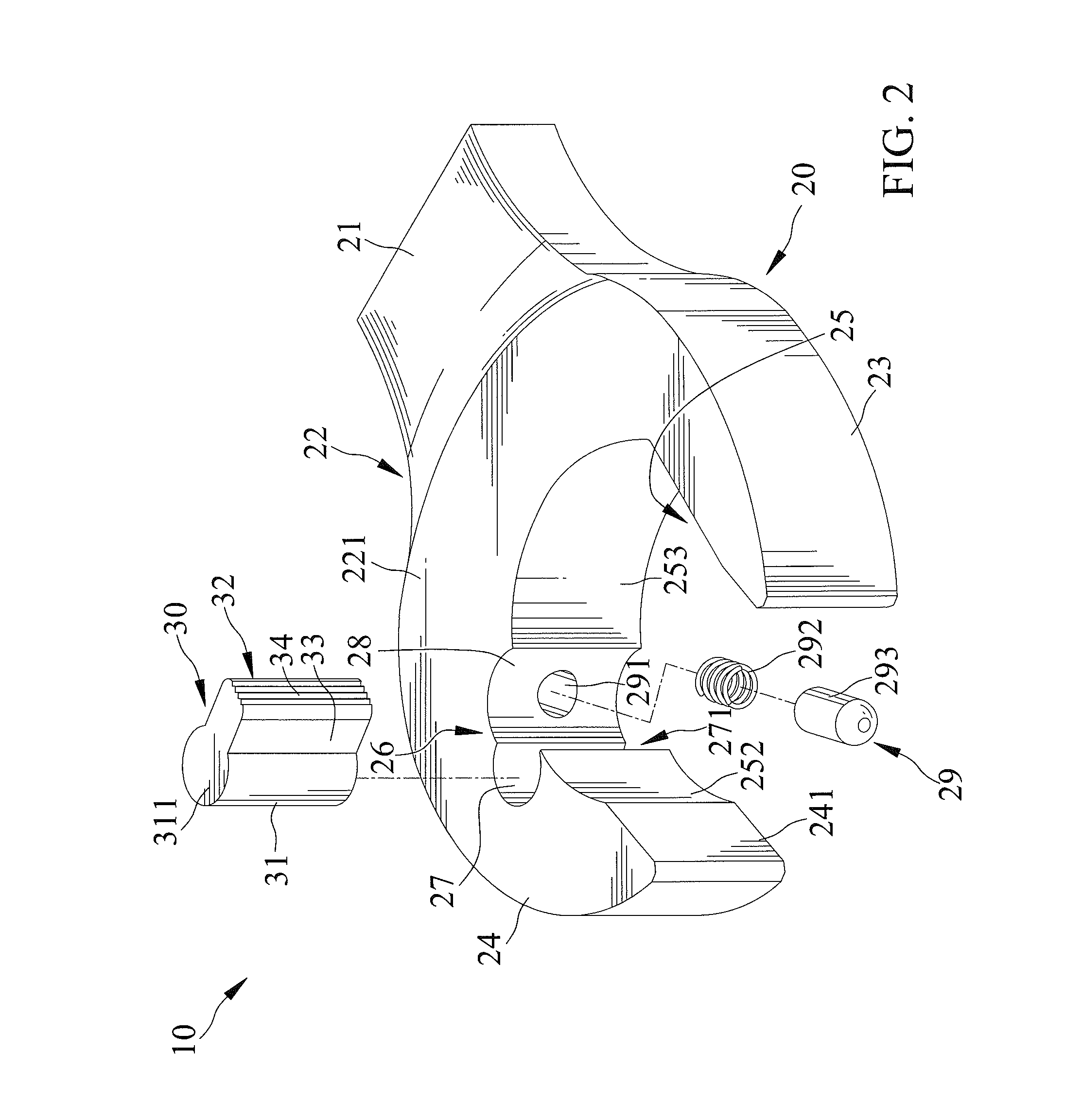
[0034]FIGS. 1 through 10 show a simple open-end wrench 10 in accordance with a first embodiment of the present invention. The open-end wrench 10 has a body 20. The body 20 includes a handle section 21 and a driving head 22. The driving head 22 includes first and second jaws 23 and 24. An engaging area 25 delimits a space 251 for receiving an object 90 to be driven by the open-end wrench 10. The space 251 is delimited between the first and second jaws 23 and 24. One of the first and second jaws 23 and 24 defines first and second lateral sides 231 and 232 delimiting the space 251. The first and second lateral side 231 and 232 are adjacent to and angled with each other with an included angle θ less than 180 degrees. The other of the first and second jaws 23 and 24 defines a third lateral side 241 facing opposite and substantially parallel with the first lateral side 231 of the first jaw 23. First and second arcuate edges 252 and 253 also delimit the space 251. The first arcuate edge 25...


PUM


Abstract

A simple open-end wrench includes a driving head including first and second jaws, a space delimited between the first and second jaws, first and second recesses extended from the space, a pawl pivotally embedded in the first recess, and a biasing mechanism received in the second recess and abutted against the pawl. The pawl includes an abutting end disposed outside the second recess and extended into the space. The pawl is pivotal to a position with the abutting end thereof disposed within the second recess.

Description

BACKGROUND OF THE INVENTION[0001]1. Field of the Invention[0002]The present invention relates to an open-end wrench and, in particular, to an open-end wrench including a ratchet mechanism.[0003]2. Description of the Related Art[0004]U.S. Pat. No. 2,700,315, entitled open-end ratchet wrench, shows a wrench including a head with a slot. Two dogs are respectively disposed at two sides of the slot. Each dog is pivotally engaged in a recess with a pivot and is pivotal relative to the head. Each dog is subject to a biasing force of a spring, which facilitates the dog to return to its original position. A shaft is used to fix each spring. However, each dog does not have a strong structure, because it is made with a through hole for pivot. A larger shear force can cause the pivot to break, because the pivot is limited to have a relatively small cross-sectional area. Therefore, the ratchet wrench can't withstand a large torque transmission well. The present invention is, therefore, intended ...

Claims


Application Information

Patent Timeline
Patent Type & Authority Patents(United States)
IPC IPC(8): B25B13/08B25B13/46
CPCB25B13/08B25B13/46
Inventor HUANG, PING-WEN
Owner CHILI DEV CO LTD
Why Eureka
Eureka Blog
Learn More