
System, garment and method

a technology applied in the field of system and garment, can solve the problems of poor circulation, affecting the ability of the body to heal, and not being suitable for elderly or frail persons or extended wearing, and devices are shoe inserts and therefore only effectiv

Active Publication Date: 2015-11-17
SENSORIA
View PDF85 Cites 28 Cited by
  • Summary
  • Abstract
  • Description
  • Claims
  • Application Information

AI Technical Summary

Benefits of technology

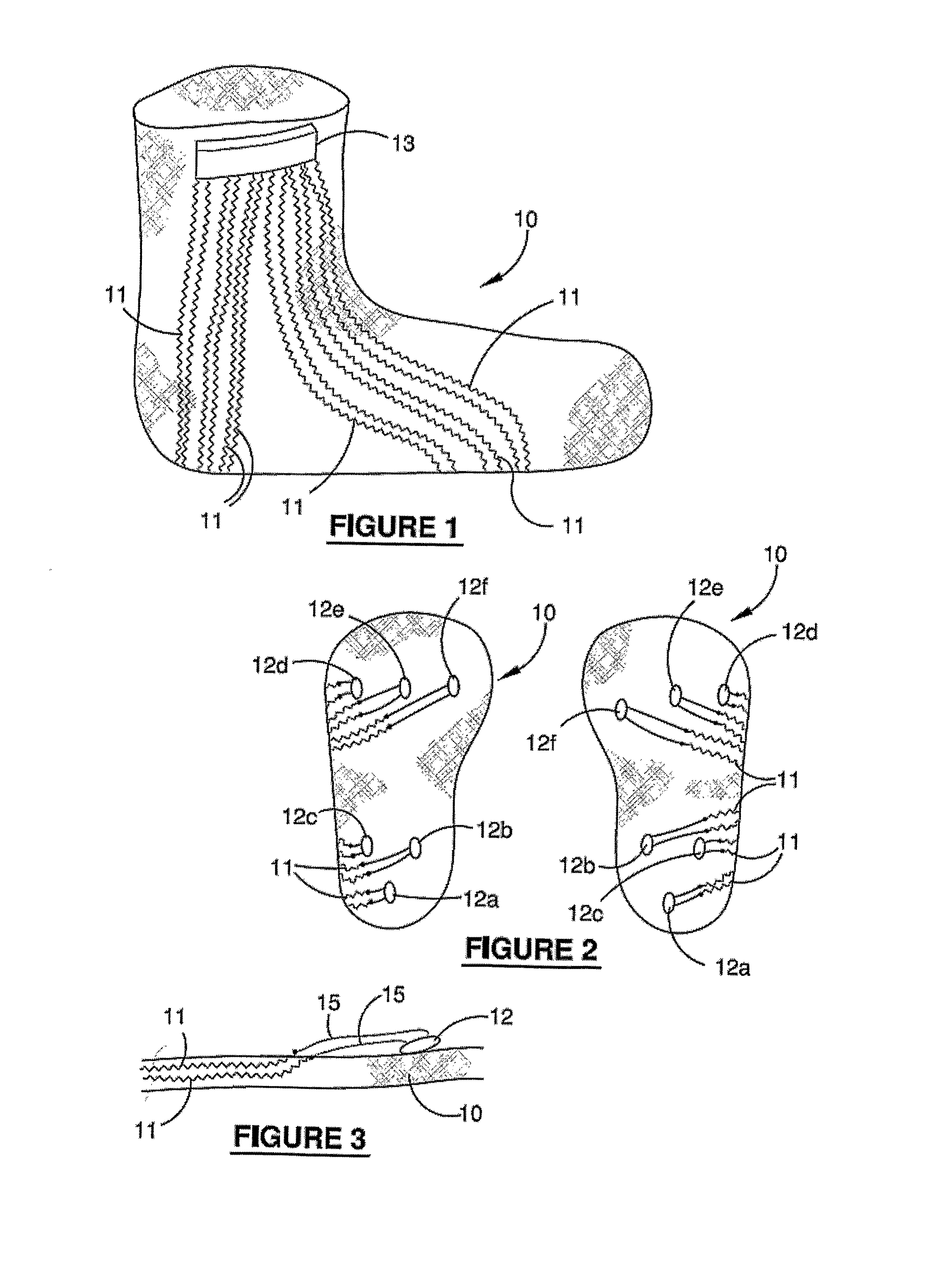
[0022]One of the advantages of the present invention is that the sensors may be strategically located to sense and monitor changes to a foot or limb condition throughout daily activity. In the instance when the invention is being used to monitor the pressure or forces on a person's foot, a clinician can position the sensors based on their understanding of the walking characteristics of the user to obtain the most relevant data from the sensors. In other words, the invention allows a level of customization to be achieved for individual users.
[0028]wherein the substrate and sensors can be worn directly or indirectly against surfaces of the user and the sensors can be positioned at desired locations without causing an increase in pressure in the load bearing surfaces as result of the presence of the pressure sensors.
[0039]wherein the substrate and pressure sensors can be worn directly or indirectly against surfaces of the user and the sensors can be positioned at desired locations without causing an increase in pressure in the surfaces of the sensors.
[0047]The ability of the sensor to not cause an increase in pressure at the surface of a user subject to loads or pressure may be achieved by a number of ways. For example, the substrate may contain recesses that house the sensors so as to provide a continuous smooth outer surface and the housing and sensors have substantially the same hardness or compression characteristics so as to maintain a relative smooth surface when the substrate is under load. However, rather than providing recesses in the substrate that accommodate the sensors, preferably the sensors have a low profile that is equal to or less than 5.0 mm in thickness, even more preferably equal to or less than 3.0 mm in thickness, and suitably less than or equal to 1.0 mm in thickness.
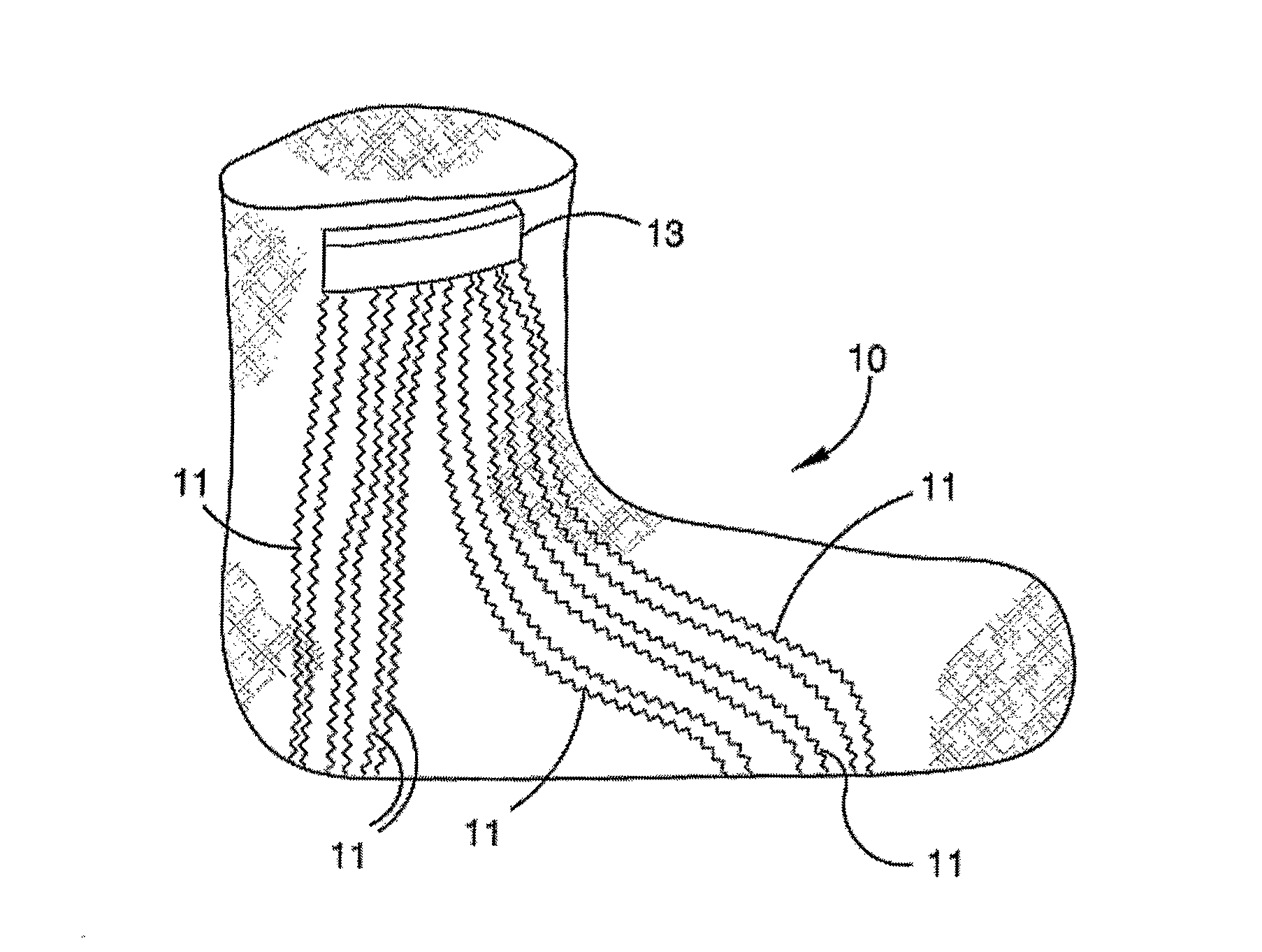
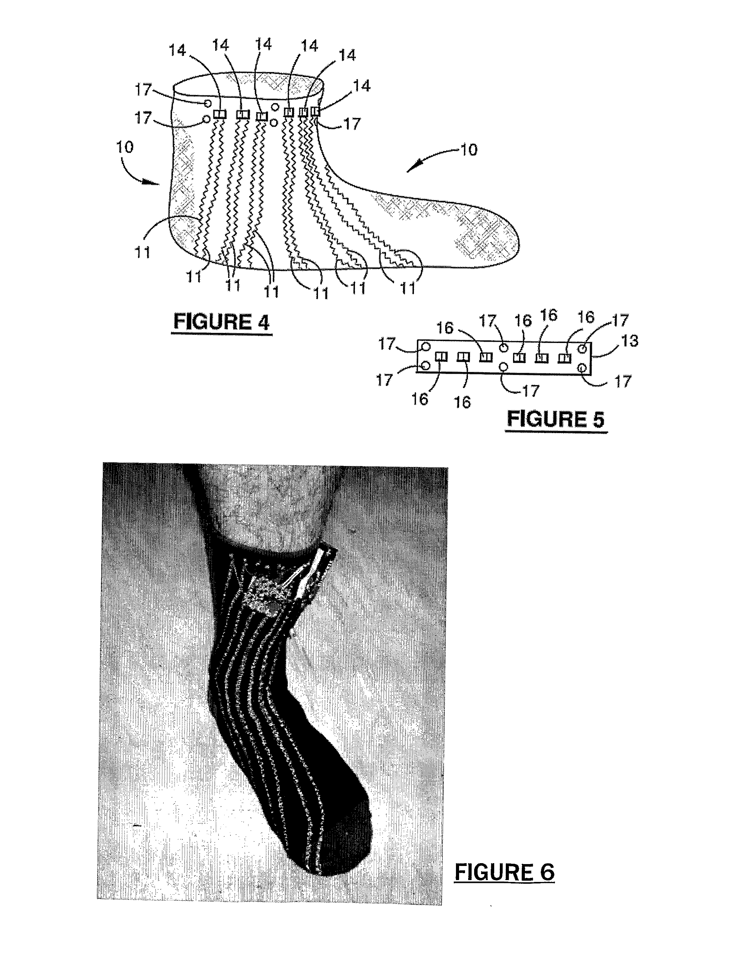
[0057]The substrate may be any form of garment depending on the particular application and body part being monitored such as socks, stockings, underpants, long johns, a singlet or a tubular sleeve. In the situation where feet of a diabetic or the stumps of an amputee are being monitored to prevent, for example, the formation of ulcers, preferably the substrate is in the form of a sock or stocking. The sock or stocking may be made from any suitable material and have any structure including knitted, woven or non-woven structures. It is also possible that the substrate may be in the form of an insert, bandage, sleeve, flexible planar materials, pads or inner garments that covers a foot or limb of a user. One of the advantages of this embodiment is that pressure sensors can be used to effectively measure the pressures applied by the bandages and thus provide a valuable means to determine the pressure gradient created by any pressure bandaging system. Applications involving monitoring and controlling pressure gradients produced through pressure bandages can be used for treating venous leg ulcers or lymphoedema. In addition, the pressure sensors can also provide a means to determine the performance of pressure bandaging on patients while the bandages are in use and the effect on the patient when moving from supine to standing positions.

Problems solved by technology

Poor circulation can affect the ability of the body to heal when damage occurs.
However, the system is not suitable for elderly or frail persons or extended wearing by persons with venous illnesses such as diabetes.
The other serious limitation is that these devices are shoe inserts and are therefore only effective when the person is wearing shoes.

Method used


Image

  • System, garment and method
  • System, garment and method
  • System, garment and method

Examples


Embodiment Construction

[0046]A series of preferred features that may apply equally to both the system, garment and method embodiments of the invention will now be described.

[0047]The ability of the sensor to not cause an increase in pressure at the surface of a user subject to loads or pressure may be achieved by a number of ways. For example, the substrate may contain recesses that house the sensors so as to provide a continuous smooth outer surface and the housing and sensors have substantially the same hardness or compression characteristics so as to maintain a relative smooth surface when the substrate is under load. However, rather than providing recesses in the substrate that accommodate the sensors, preferably the sensors have a low profile that is equal to or less than 5.0 mm in thickness, even more preferably equal to or less than 3.0 mm in thickness, and suitably less than or equal to 1.0 mm in thickness.

[0048]Even more preferably, the sensors have a thickness that is equal to or less than 0.5 m...


PUM


Abstract

The present invention relates to a system and garment that incorporates sensors that can be used for measuring or monitoring pressure or forces in feet, the stumps of limbs of an amputee that are fitted with prosthetic devices, or any other parts of the body that are subject to forces such as the buttock while seated or when external pressure inducing devices are employed, such as for example, pressure bandages. The invention also relates to a method to monitor or diagnose any foot or limb related activity for recreational, sporting, military or medical reasons and is particularly aimed at the treatment of neuropathic or other degenerating conditions.

Description

[0001]This application is a filing under 35 U.S.C. §371 of International Patent Application PCT / AU2008 / 001245, filed Aug. 22, 2008, which claims priority to Australian Application No. 2007904520, filed Aug. 22, 2007, the entirety of each is hereby incorporated herein by reference.FIELD AND BACKGROUND OF THE PRESENT INVENTION[0002]The present invention relates to a system and garment that incorporates sensors that can be used for measuring or monitoring pressure or forces in feet, the stumps of limbs of an amputee that are fitted with prosthetic devices, or any other parts of the body that are subject to forces such as the buttock while seated or when external pressure inducing devices are employed, for example, pressure bandages. The invention may also incorporate other sensors for monitoring physical conditions such as temperature, strain, stress or angulation or sensors for monitoring physiological conditions such as the make up of sweat or body exudate. Moreover, the invention al...

Claims


Application Information

Patent Timeline
Patent Type & Authority Patents(United States)
IPC IPC(8): A61B5/103A61B5/01A61B5/00
CPCA61B5/1038A61B5/6807A61B5/01A61B5/4261A61B5/112A61B5/1121A61B5/14517
Inventor MESTROVIC, MICHAEL ANTHONYPETERSEN, PAMELA MARGARETCRANSTON, ROBIN WILLIAMSTANNARD, WARREN BRADLEYD'ARCY, PATRICK BRENDAN
Owner SENSORIA
Learn More