Automatic point-wise validation of respiratory motion estimation

a motion estimation and point-wise validation technology, applied in the field of automatic point-wise validation of respiratory motion estimation, can solve the problems of reducing introducing incorrect deformations, and unable to guarantee the success of registration, so as to reduce the probability of positive validation

Active Publication Date: 2015-10-27
KONINK PHILIPS ELECTRONICS NV
View PDF8 Cites 9 Cited by
  • Summary
  • Abstract
  • Description
  • Claims
  • Application Information

AI Technical Summary

Benefits of technology

[0005]It would be useful to provide a validation scheme for reducing the likelihood of positive validation of an erroneously estimated DVF.
[0013]In an embodiment of the system, the conformity measure is computed at the plurality of locations, based on the computed metric of the local volume change at the plurality of locations and the local property of the first or second image defined at the plurality of locations, thereby becoming a conformity map. For example, the metric of the local volume change may be the Jacobian metric, the local property may be the image-intensity-based metric, and, at each location of the plurality of locations, the conformity measure may be the absolute value of the difference of the Jacobian metric and the intensity metric at said location. The conformity map allows validating the motion estimation locally, at the plurality of locations.

Problems solved by technology

However, the absence of any structure in the residuum image does not guarantee a successful registration since the residuum is invariant to the deformation of homogeneous image regions.
Unfortunately, it often introduces incorrect deformations, even folding, into the DVF.
Therefore, using a residuum image for validating a DVF may often lead to an erroneous determination of the DVF.

Method used


Image

  • Automatic point-wise validation of respiratory motion estimation
  • Automatic point-wise validation of respiratory motion estimation
  • Automatic point-wise validation of respiratory motion estimation

Examples


Embodiment Construction

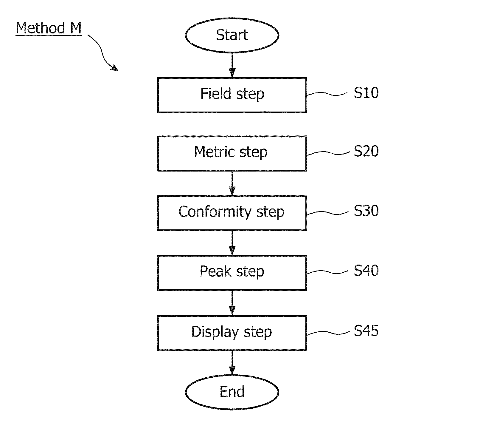
[0041]FIG. 1 schematically shows a block diagram of an exemplary embodiment of the system 100 for validating motion estimation, comprising:

[0042]a field unit 110 for obtaining a deformation vector field estimating the motion by transforming a first image at a first phase of the motion into a second image at a second phase of the motion;

[0043]a metric unit 120 for computing a metric of a local volume change at a plurality of locations; and

[0044]a conformity unit 130 for computing a conformity measure, based on the computed metric of the local volume change at the plurality of locations and a local property of the first or second image defined at the plurality of locations.

[0045]The exemplary embodiment of the system 100 further comprises:

[0046]a peak unit 140 for detecting peaks in the conformity map;

[0047]an update unit 150 for updating the deformation vector field, based on the computed conformity measure.

[0048]a control unit 160 for controlling the work of the system 100;

[0049]a u...


PUM


Abstract

A system for validating motion estimation comprising a field unit (110) for obtaining a deformation vector field (DVF) estimating the motion by transforming a first image at a first phase of the motion into a second image at a second phase of the motion, a metric unit (120) for computing a metric of a local volume change at a plurality of locations, and a conformity unit (130) for computing a conformity measure based on the computed metric of the local volume change at the plurality of locations and a local property of the first or second image defined at the plurality of locations. Based on the value of the conformity measure, the DFV estimating the motion is validated. Experiments show that the conformity measure based on the computed metric of a local volume change at a plurality of locations and the local property of the first or second image, defined at the plurality of locations, does not necessarily favor a large weight for the outer force to provide a more accurate registration. One reason for this observation may be that large deformations providing more accurate alignment often lead to deformations resulting in unreasonably large volume changes. DVFs comprising such deformations thus are more likely to be discarded by the system of the invention.

Description

FIELD OF THE INVENTION[0001]In general, this invention relates to automatic point-wise validation of motion estimation, wherein the motion is estimated by a deformation vector field for transforming a first image at a first phase of the motion into a second image at a second phase of the motion. In particular, this invention relates to automatic point-wise validation of respiratory motion estimation on the basis of CT images.BACKGROUND OF THE INVENTION[0002]Compensating body motion in medical imaging is a necessity and has already become indispensable in this area. Since motion compensation by rigid or affine transformations is suitable only for few clinical target applications (e.g. patient positioning for brain applications), motion compensation by a non-rigid or elastic transformation has become state-of-the-art. A prominent example for the usefulness of an elastic transformation is respiratory motion.[0003]Motion compensation requires the registration of at least two images for ...

Claims


Application Information

Patent Timeline
Patent Type & Authority Patents(United States)
IPC IPC(8): G06K9/00G06T7/00G06T3/00G06T7/20
CPCG06T7/20G06T3/0081G06T7/0016G06T7/0024G06T2207/10081G06T2207/30061G06T7/30
Inventor KABUS, SVENKLINDER, TOBIASLORENZ, CRISTIAN
Owner KONINK PHILIPS ELECTRONICS NV
Why Eureka
Try Eureka