Flat display device with alternating white image driving periods
- Summary
- Abstract
- Description
- Claims
- Application Information
AI Technical Summary
Benefits of technology
Problems solved by technology
Method used
Image
Examples
first embodiment
[0021]FIG. 1 is a block diagram illustrating an organic light emitting display device according to the present invention. The display device includes a panel driving unit 108 including a data driver 104, a scan driver 106 and a timing controller 110, and a light emitting display panel 102. The light emitting display panel 102 includes a plurality of unit pixels P each including a red sub-pixel SPR, a green sub-pixel SPG, a blue sub-pixel SPB, and a white sub-pixel SPW. Arrangement of the sub-pixels in each unit pixel P may be very diverse. The arrangement of the red sub-pixel SPR, white sub-pixel SPW, blue sub-pixel SPB, and green sub-pixel SPG illustrated in FIG. 1 is illustrative and, as such, the present invention is not limited thereto. Each of the sub-pixels SPR, SPG, SPW, and SPB is formed at a pixel region provided in accordance with intersection of one gate line GL and one data line DL.
[0022]Next, FIG. 2 illustrates each of the sub-pixels SPR, SPG, SPW, and SPB includes a sw...
second embodiment
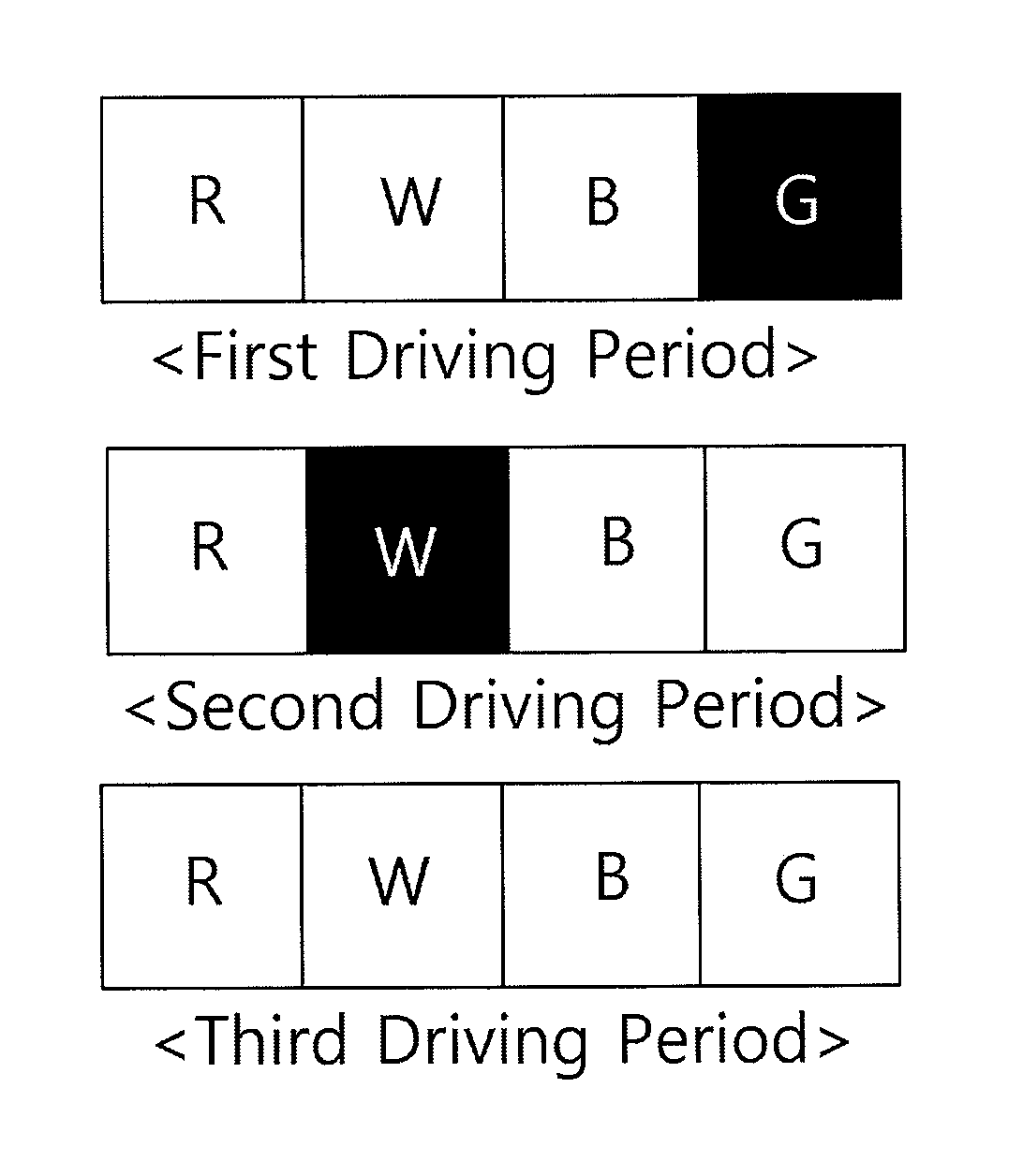
[0040]In the flat display device according to the present invention, efficiency exhibited when a white image is displayed, using the first white unit data R′W′B′ is higher than efficiency exhibited when a white image is displayed, using the second white unit data R′B′G′. Accordingly, the first driving period, t1, in which a white image is rendered, using the first white unit data R′W′B′, is set to be longer than the second driving period, t2, in which white image is displayed, using the second white unit data R′B′G′. That is, the first and second driving periods t1 and t2 are determined to be proportional to the ratio between efficiency E1 exhibited when a white image is displayed, using the first white unit data R′W′B′ and efficiency E2 exhibited when a white image is displayed, using the second white unit data R′B′G′ (E1:E2=t1:t2).
[0041]To this end, the timing controller 110 in the flat display device according to the second embodiment of the present invention includes a control s...
third embodiment
[0050]The timing controller 110 in the flat display device according to the present invention includes a control signal generator 120, a four-color data transformer 112, a unit pixel information unit 114, a power sensor 124, a power counter 126, and a pixel data processor 118. The control signal generator 120, four-color data transformer 112, and unit pixel information unit 114 are similar to those of FIG. 3.
[0051]The power sensor 124 senses turning-on or off of power of the display panel, and generates a sensing signal, based on results of the sensing operation. The power counter 126 counts sensing signals PSS from the power sensor 124, and supplies the first and second white drive signals WDS1 and WDS2 to the pixel data processor 118, based on results of the counting operation. In detail, when the power sensor 124 senses turning-off of power, the power counter 126 counts sensing signals PSS. When an odd number of sensing signals PSS is counted, the power counter 126 supplies the s...
PUM
 Abstract
Description
Claims
Application Information
 - R&D
- Intellectual Property
- Life Sciences
- Materials
- Tech Scout
- Unparalleled Data Quality
- Higher Quality Content
- 60% Fewer Hallucinations
Browse by: Latest US Patents, China's latest patents, Technical Efficacy Thesaurus, Application Domain, Technology Topic, Popular Technical Reports.
© 2025 PatSnap. All rights reserved.Legal|Privacy policy|Modern Slavery Act Transparency Statement|Sitemap|About US| Contact US: help@patsnap.com


