
Micromixer combustion head end assembly

a micro-mixer and combustion head technology, applied in the direction of dispersed particle separation, lighting and heating apparatus, separation processes, etc., can solve the problems of reducing the mixing of fuel and air, reducing the combustion temperature and nox emissions output, and increasing undesirable levels of emissions

Active Publication Date: 2015-10-20
GENERAL ELECTRIC CO
View PDF29 Cites 16 Cited by
  • Summary
  • Abstract
  • Description
  • Claims
  • Application Information

AI Technical Summary

Benefits of technology

The present patent application describes a micromixer which includes a base nozzle structure, coaxial tubes, and segmented mixing tube bundles. The micromixer may also have an end cap assembly. The technical effect of this design is to provide a compact and efficient mixing device that allows for precise control of mixing of liquids and gases.

Problems solved by technology

Higher combustion gas stream temperatures, however, may produce higher levels of undesirable emissions such as nitrogen oxides (NOx) and the like.
Such premixing tends to reduce combustion temperatures and NOx emissions output.
In current micromixer designs, there may be multiple fuel feeds and / or liquid cartridge or blank feeds that obstruct air flow and decrease the mixing of fuel and air.

Method used


Image

  • Micromixer combustion head end assembly
  • Micromixer combustion head end assembly
  • Micromixer combustion head end assembly

Examples


Embodiment Construction

[0017]Illustrative embodiments will now be described more fully hereinafter with reference to the accompanying drawings, in which some, but not all embodiments are shown. The present application may be embodied in many different forms and should not be construed as limited to the embodiments set forth herein. Like numbers refer to like elements throughout.

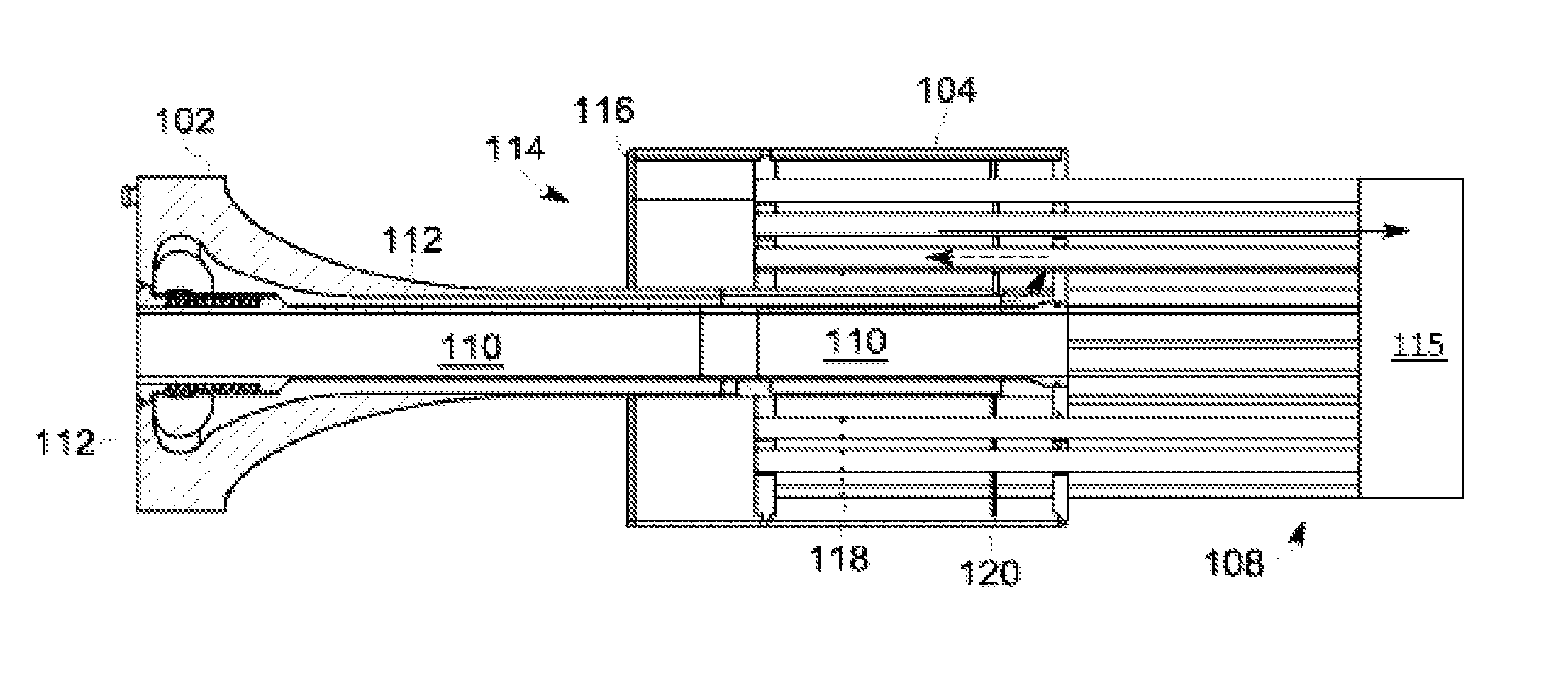
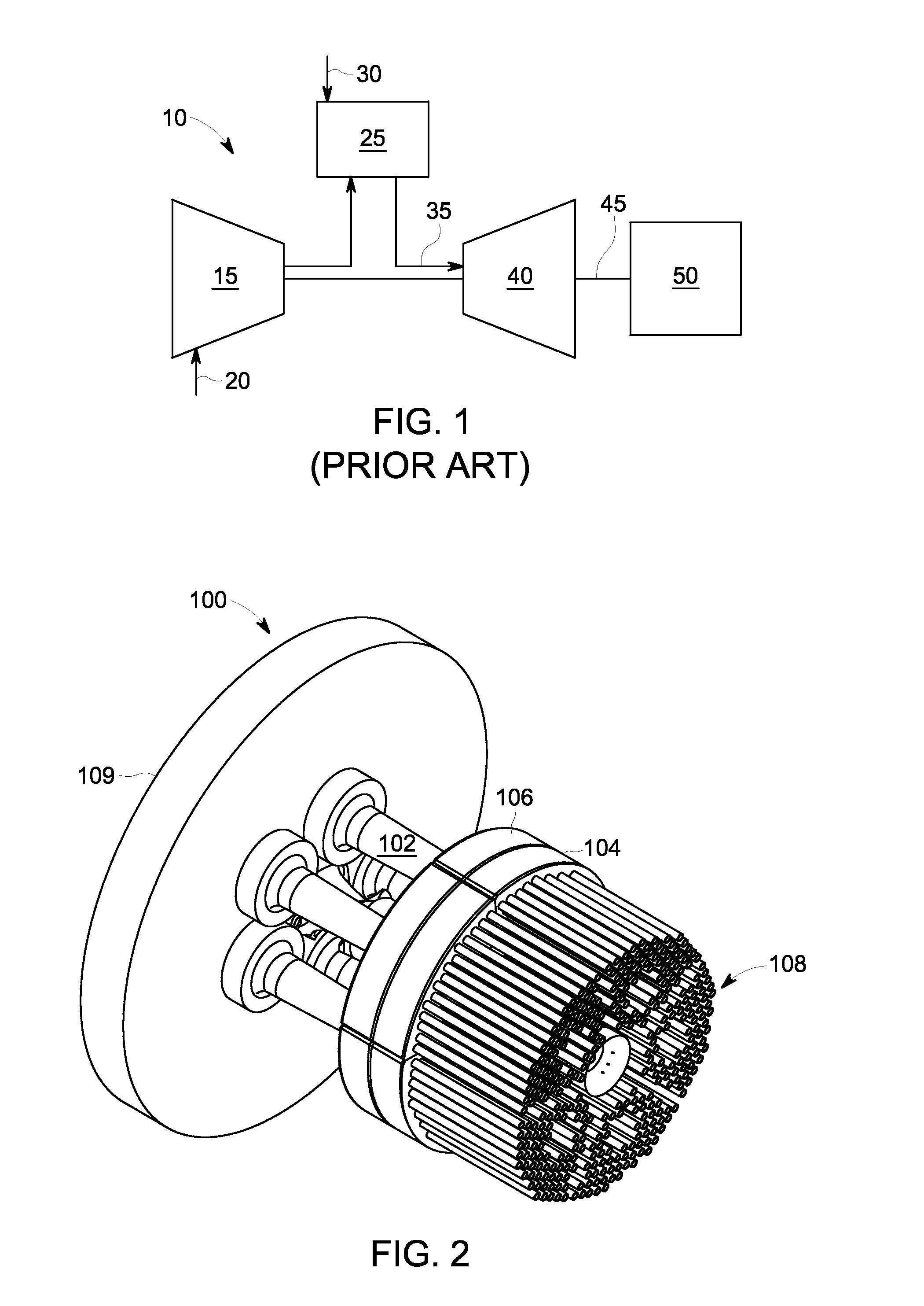
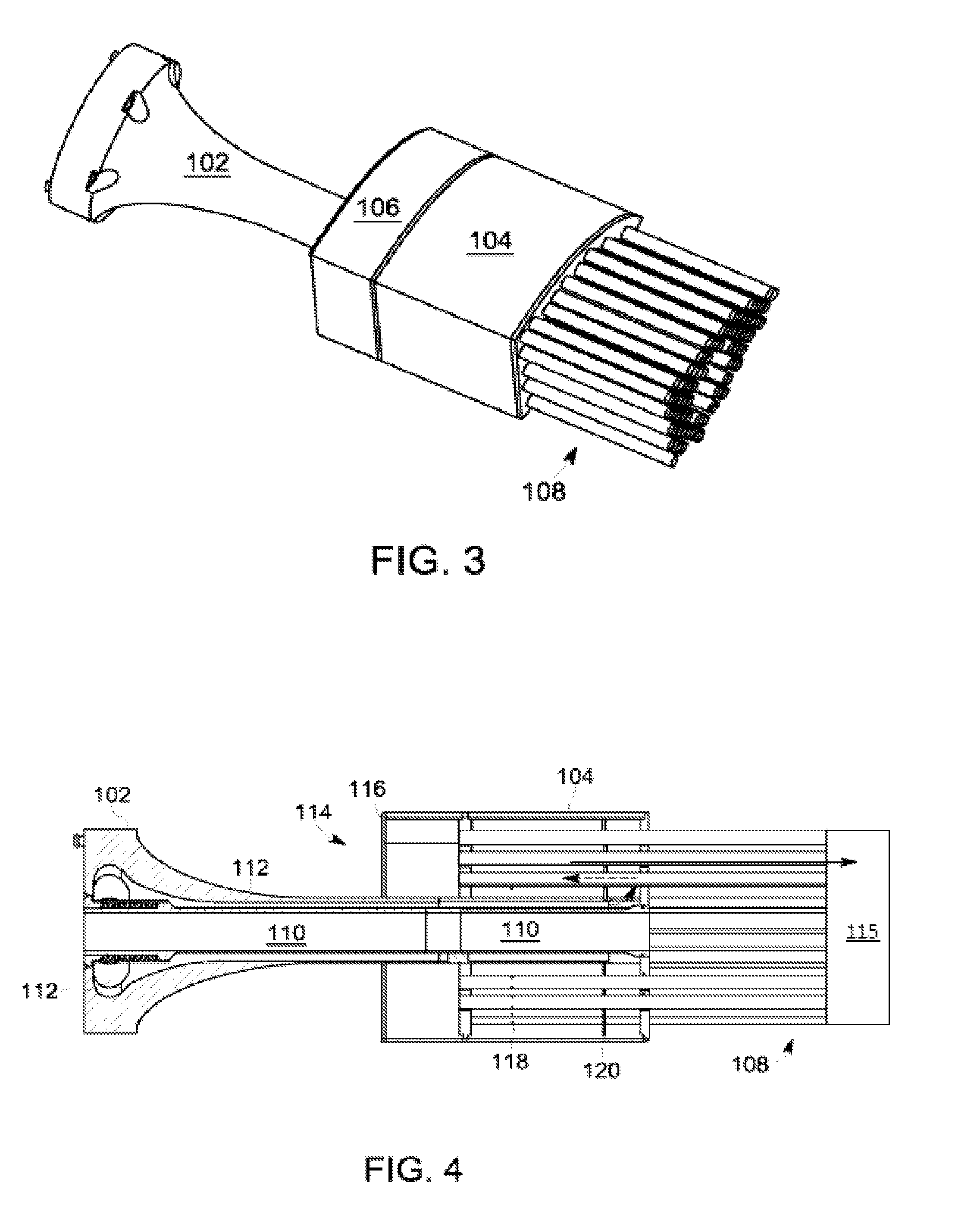
[0018]Illustrative embodiments are directed to, among other things, micromixers for a combustor. FIG. 1 shows a schematic view of a gas turbine engine 10 as may be used herein. As is known, the gas turbine engine 10 may include a compressor 15. The compressor 15 compresses an incoming flow of air 20. The compressor 15 delivers the compressed flow of air 20 to a combustor 25. The combustor 25 mixes the compressed flow of air 20 with a pressurized flow of fuel 30 and ignites the mixture to create a flow of combustion gases 35. Although only a single combustor 25 is shown, the gas turbine engine 10 may include any number of combustors...


PUM

PropertyMeasurementUnit
temperatureaaaaaaaaaa
temperaturesaaaaaaaaaa
combustion temperaturesaaaaaaaaaa

Abstract

Embodiments of the present application can provide systems and methods for a micromixer combustion head end assembly. The micromixer may include one or more base nozzle structures. The base nozzle structures may include coaxial tubes. The coaxial tubes may include an inner tube and an outer tube. The micromixer may also include one or more segmented mixing tube bundles at least partially supported by a respective base nozzle structure. Moreover, the micromixer may include an end cap assembly disposed about the one or more segmented mixing tube bundles.

Description

FIELD OF THE INVENTION[0001]Embodiments of the present application relate generally to gas turbine engines and more particularly to micromixers.BACKGROUND OF THE INVENTION[0002]Gas turbine efficiency generally increases with the temperature of the combustion gas stream. Higher combustion gas stream temperatures, however, may produce higher levels of undesirable emissions such as nitrogen oxides (NOx) and the like. NOx emissions generally are subject to governmental regulations. Improved gas turbine efficiency therefore must be balanced with compliance with emissions regulations.[0003]Lower NOx emission levels may be achieved by providing for good mixing of the fuel stream and the air stream. For example, the fuel stream and the air stream may be premixed in a Dry Low NOx (DLN) combustor before being admitted to a reaction or a combustion zone. Such premixing tends to reduce combustion temperatures and NOx emissions output.[0004]In current micromixer designs, there may be multiple fu...

Claims


Application Information

Patent Timeline
Patent Type & Authority Patents(United States)
IPC IPC(8): B01F3/04F23R3/28
CPCF23R3/286
Inventor WESTMORELAND, JAMES HAROLDMELTON, PATRICK BENEDICT
Owner GENERAL ELECTRIC CO
Learn More