
Distributed capacitance radio frequncy (RF) coil and magnetic resonance imaging system including the same

a technology of distributed capacitance and magnetic resonance imaging, which is applied in the field of magnetic resonance imaging systems, can solve problems such as the event of failure of the rf coil

Active Publication Date: 2015-10-13
GENERAL ELECTRIC CO
View PDF11 Cites 6 Cited by
  • Summary
  • Abstract
  • Description
  • Claims
  • Application Information

AI Technical Summary

Benefits of technology

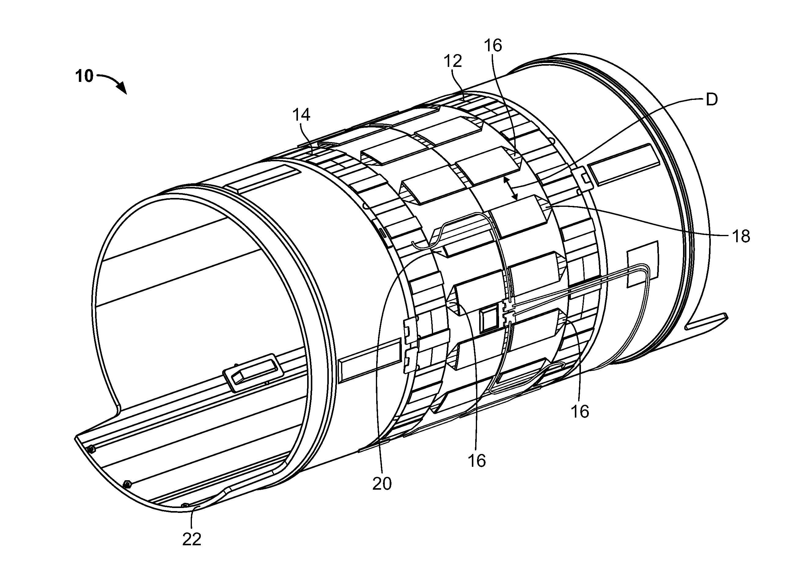
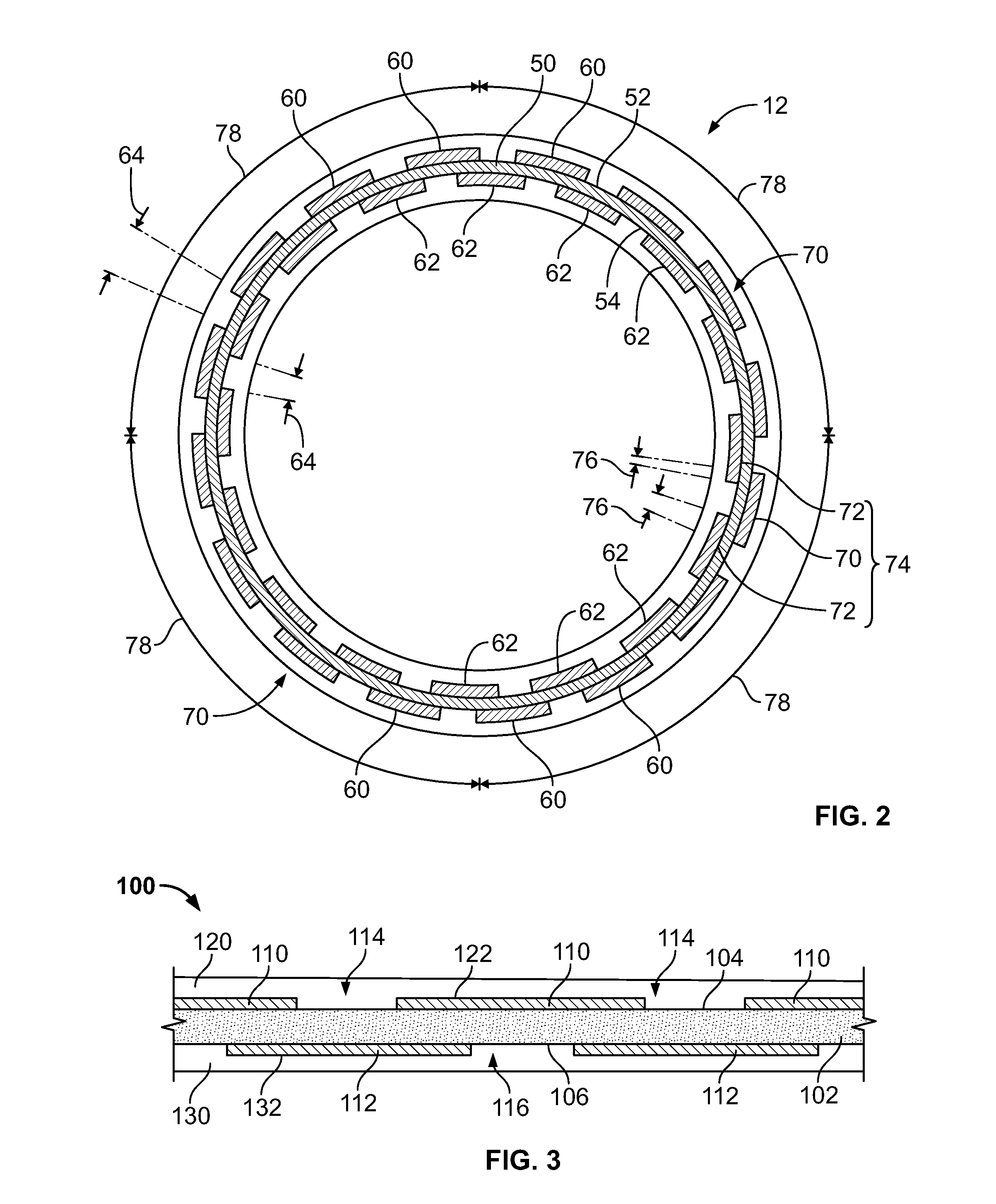
The present patent text describes a radio frequency (RF) birdcage coil and methods for its fabrication. The coil has several rungs connected between two end rings, with each rung having a substrate with conductors formed on its sides. An insulating material is deposited on the substrate to protect the conductors. The end rings can have different conductor patterns. The method involves depositing layers of metal and an insulating layer onto the substrate. The technical effects of the invention are improved RF signal transmission and reduced interference between the coil's components.

Problems solved by technology

Thus, when the RF coil reaches the breakdown voltage, ionization of the air in the gaps may result in arcing to occur between various portions of the birdcage coil which may result in an eventual failure of the RF coil.

Method used


Image

  • Distributed capacitance radio frequncy (RF) coil and magnetic resonance imaging system including the same
  • Distributed capacitance radio frequncy (RF) coil and magnetic resonance imaging system including the same
  • Distributed capacitance radio frequncy (RF) coil and magnetic resonance imaging system including the same

Examples


Embodiment Construction

[0016]Embodiments of the invention will be better understood when read in conjunction with the appended drawings. To the extent that the figures illustrate diagrams of the functional blocks of various embodiments, the functional blocks are not necessarily indicative of the division between hardware circuitry. Thus, for example, one or more of the functional blocks (e.g., processors, controllers or memories) may be implemented in a single piece of hardware (e.g., a general purpose signal processor or random access memory, hard disk, or the like) or multiple pieces of hardware. Similarly, the programs may be stand alone programs, may be incorporated as subroutines in an operating system, may be functions in an installed software package, and the like. It should be understood that the various embodiments are not limited to the arrangements and instrumentality shown in the drawings.

[0017]As used herein, an element or step recited in the singular and proceeded with the word “a” or “an” s...


PUM


Abstract

A radio frequency (RF) birdcage coil includes a first distributed capacitance end ring, a second distributed capacitance end ring, and a plurality of rungs connected between the first and second end rings, wherein at least one of the first and second distributed capacitance end rings includes a substrate having a first side and a second side, a first plurality of conductors formed on the first side, a second plurality of conductors formed on the second side, and an insulating material deposited on the first side such that the insulating material substantially covers the first plurality of conductors.

Description

BACKGROUND OF THE INVENTION[0001]The subject matter disclosed herein relates generally to magnetic resonance imaging (MRI) systems, and more particularly to a distributed capacitance radio frequency (RF) coil for MRI systems.[0002]MRI is a medical imaging modality that generates images of the inside of a human body without using x-rays or other ionizing radiation. MRI uses a magnet to create a strong, uniform, static magnetic field (i.e., the “main magnetic field”) and gradient coils to produce smaller amplitude, spatially varying magnetic fields when a current is applied to the gradient coils. When a human body, or part of a human body, is placed in the main magnetic field, the nuclear spins that are associated with hydrogen nuclei in tissue water become polarized. The magnetic moments that are associated with these spins become preferentially aligned along the direction of the main magnetic field, resulting in a small net tissue magnetization along that axis (the “z axis,” by conv...

Claims


Application Information

Patent Timeline
Patent Type & Authority Patents(United States)
IPC IPC(8): G01R33/34
CPCG01R33/34007G01R33/34076
Inventor SHAH, BIJAYBECERRA, RICARDOFUJIMOTO, MASAHIROXIE, ZHENTIANEDWARDS, MICHAEL P.
Owner GENERAL ELECTRIC CO
Learn More