Method for operating flash memories on a bus

a bus and flash memory technology, applied in the field of flash memory operation, can solve the problems of inconvenient operation of the bus, inability to achieve the best efficiency of operating two flash memories, and the idle time of the bus

Inactive Publication Date: 2015-10-06
ETRON TECH INC
View PDF6 Cites 3 Cited by
  • Summary
  • Abstract
  • Description
  • Claims
  • Application Information

AI Technical Summary

Benefits of technology

[0008]The present invention provides a method for operating flash memories on a bus. Sequence of operation for flash memories on the bus is enabling the read command of the first flash memory, enabling the read command of the second flash memory, reading the data of the first flash memory, enabling the read command of the first flash memory, reading the data of the second flash memory, enabling the read command of the second flash memory, reading the data of the first flash memory, enabling the read command of the first flash memory, and so on. Only at the beginning of the sequence of the operation for the flash memories are enabling the read command of the first flash memory and enabling the read command of the second flash memory performed together, then the present invention repeats steps of reading the data of the first flash memory, enabling the read command of the first flash memory, reading the data of the second flash memory, and enabling the read command of the second flash memory. Therefore, in the present invention, data transmitted on the bus are more compact and efficient than the prior art.

Problems solved by technology

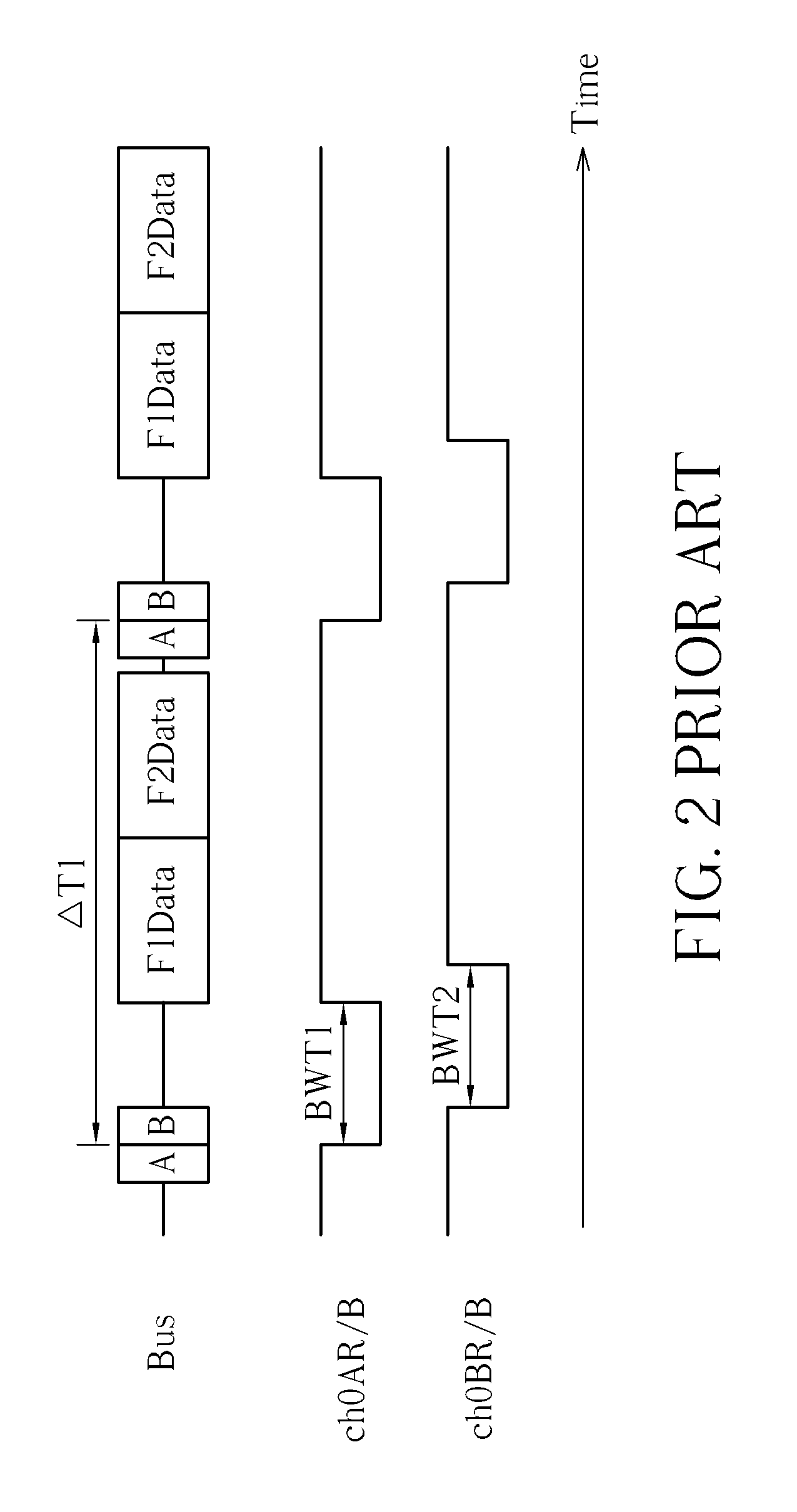
However, as shown in FIG. 2, data transmitted on the bus are not compact; that is to say, the bus has some idle time.
Therefore, operation efficiency of the prior art does not achieve the best efficiency for operating two flash memories on a bus.

Method used


Image

  • Method for operating flash memories on a bus
  • Method for operating flash memories on a bus
  • Method for operating flash memories on a bus

Examples


Embodiment Construction

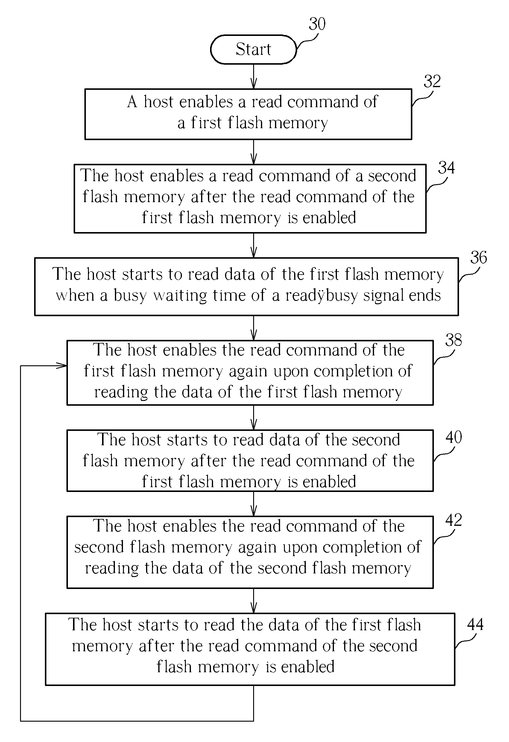
[0014]Please refer to FIG. 3 and FIG. 4. FIG. 3 is a flowchart illustrating a method for operating flash memories on a bus according to an embodiment, and FIG. 4 is a timing diagram of the method shown in FIG. 3. Detailed steps of the method shown in FIG. 3 are as follows:

[0015]Step 30: Start.

[0016]Step 32: A host enables a read command A of a first flash memory.

[0017]Step 34: The host enables a read command B of a second flash memory after the read command A of the first flash memory is enabled.

[0018]Step 36: The host starts to read data F1Data of the first flash memory when a busy waiting time BWT1 of a ready / busy signal ch0AR / B ends.

[0019]Step 38: The host enables the read command A of the first flash memory again upon completion of reading the data F1Data of the first flash memory.

[0020]Step 40: The host starts to read data F2Data of the second flash memory after the read command A of the first flash memory is enabled.

[0021]Step 42: The host enables the read command B of the sec...


PUM


Abstract

Enable a read command of a first flash memory. After the read command of the first flash memory is enabled, a ready / busy signal of the first flash memory enters a busy waiting time, and a read command of a second flash memory starts to be enabled. Start to read data of the first flash memory when the busy waiting time is over. Enable the read command of the first flash memory again upon completion of reading the data of the first flash memory. Start to read data of the second flash memory after the read command of the first flash memory is enabled again. And enable the read command of the second flash memory again upon completion of reading the data of the second flash.

Description

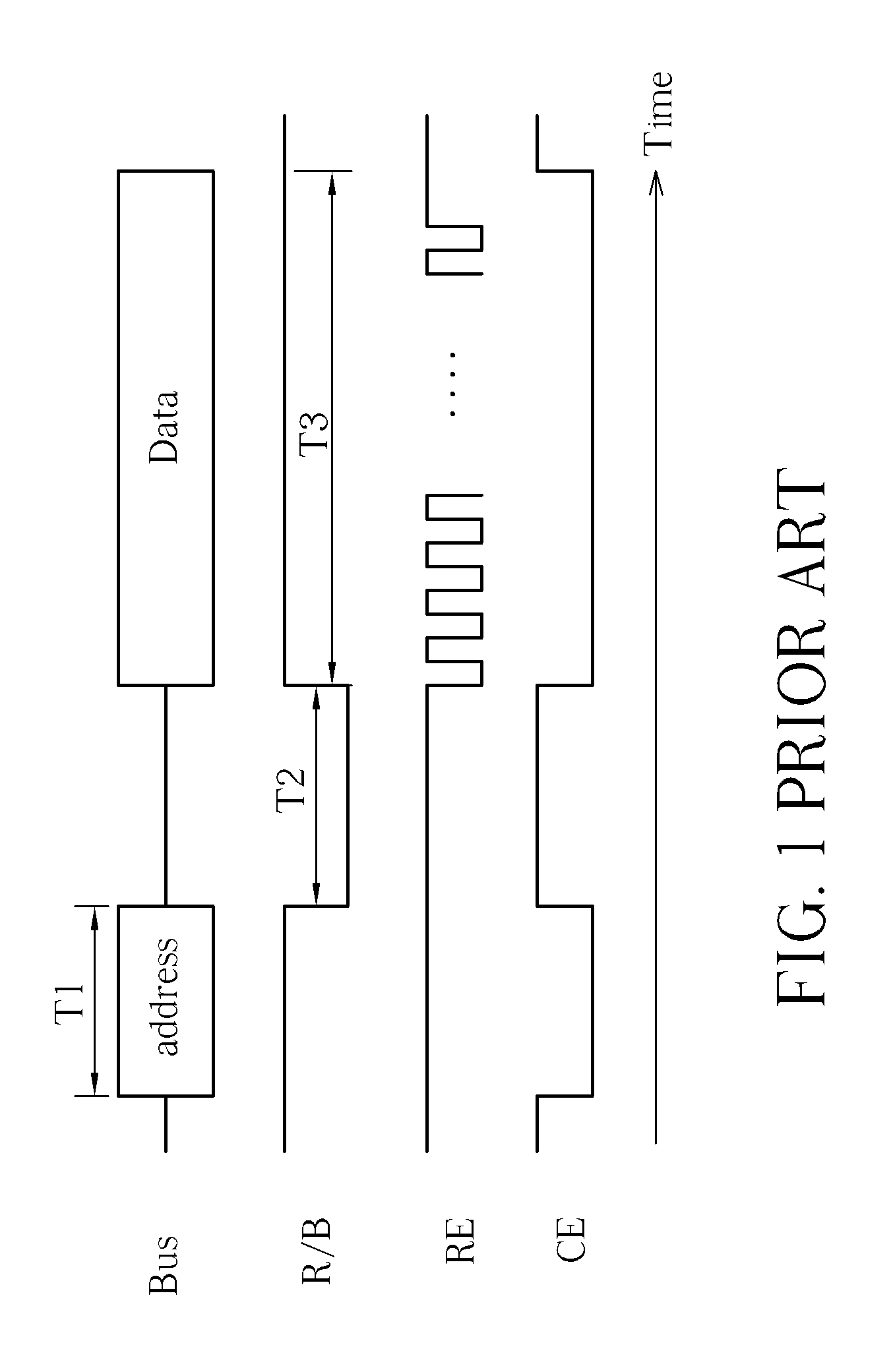
BACKGROUND OF THE INVENTION[0001]1. Field of the Invention[0002]The present invention is related to a method for operating flash memories, and particularly to a method for operating two flash memories on a bus.[0003]2. Description of the Prior Art[0004]Please refer to FIG. 1. FIG. 1 is a timing diagram illustrating a ready / busy signal R / B, a read enabling signal RE, and a chip enabling signal CE when a host reads a flash memory. As shown in FIG. 1, when a read command of the flash memory is enabled, the ready / busy signal R / B enters a busy waiting time T2. The host starts to toggle the read enabling signal RE when the busy waiting time T2 is over. The host reads data of the flash memory according to a data storing address included by the read command once each time the read enabling signal RE is toggled. When the host starts to toggle the read enabling signal RE, a chip enabling signal CE of the flash memory is changed from high to low. In addition, in an operation specification of a...

Claims


Application Information

Patent Timeline
Patent Type & Authority Patents(United States)
IPC IPC(8): G06F12/00G06F13/16G06F12/02
CPCG06F13/16G06F12/0246G06F13/4234
Inventor HSIEH, MING-HUNG
Owner ETRON TECH INC
Why Eureka
Try Eureka