Oscillating mass pivoted on the exterior of a timepiece movement, timepiece movement fitted with such an oscillating mass and timepiece comprising such an oscillating mass

Active Publication Date: 2015-09-29
CARTIER INT
View PDF25 Cites 0 Cited by
  • Summary
  • Abstract
  • Description
  • Claims
  • Application Information

AI Technical Summary

Benefits of technology

The present invention aims to create an automatic winding timepiece movement that is more powerful and effective than existing devices. This is achieved by designing an oscillating mass that can have a greater weight for the same dimensions as the movement. Additionally, the shape of the oscillating mass is designed to have a visual and aesthetic effect that is new and interesting.

Problems solved by technology

However, this embodiment has the same disadvantages as those stated above in relation to the embodiment described in document DE 10 2009 005 690.

Method used


Image

  • Oscillating mass pivoted on the exterior of a timepiece movement, timepiece movement fitted with such an oscillating mass and timepiece comprising such an oscillating mass
  • Oscillating mass pivoted on the exterior of a timepiece movement, timepiece movement fitted with such an oscillating mass and timepiece comprising such an oscillating mass
  • Oscillating mass pivoted on the exterior of a timepiece movement, timepiece movement fitted with such an oscillating mass and timepiece comprising such an oscillating mass

Examples


Embodiment Construction

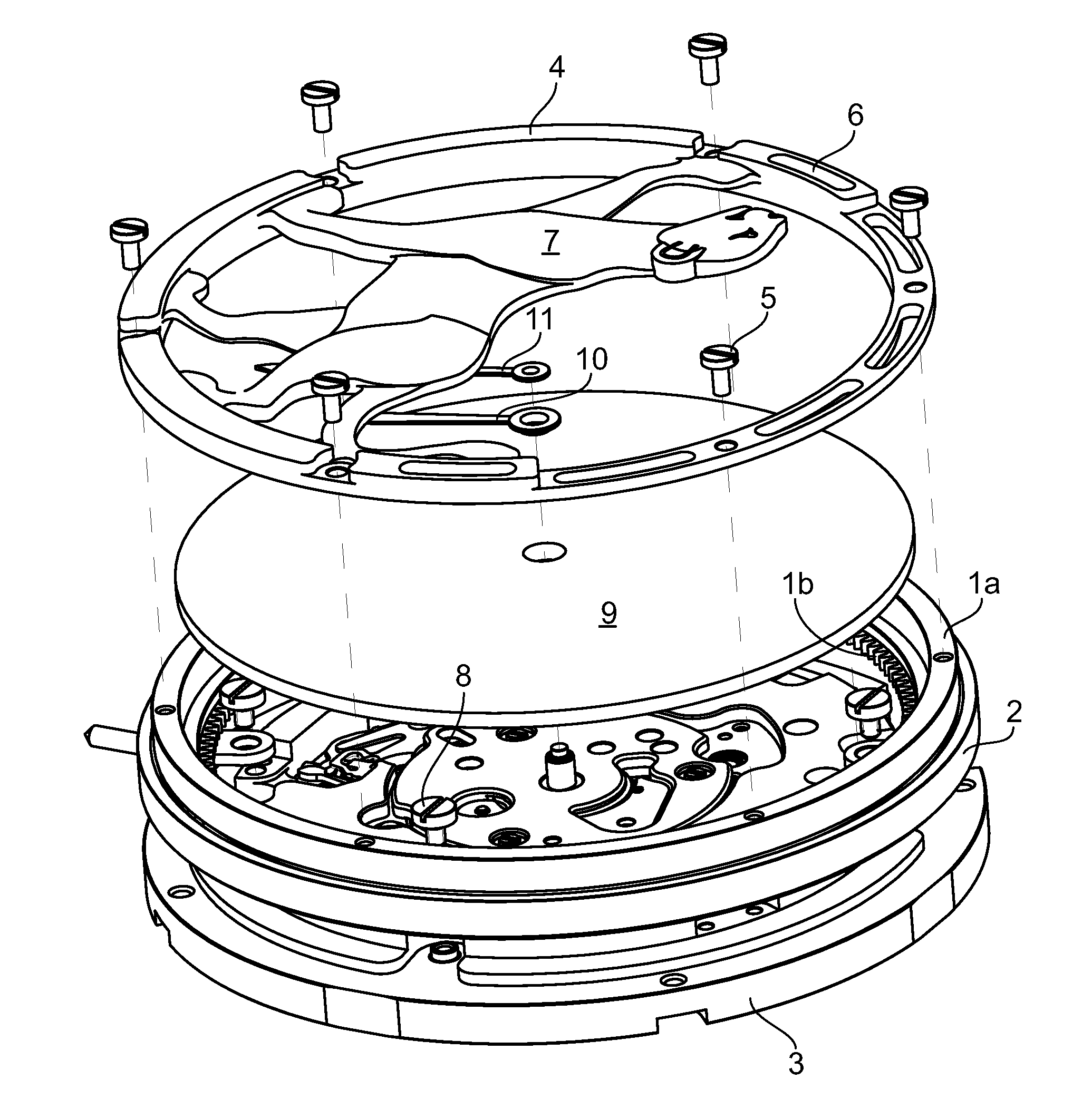
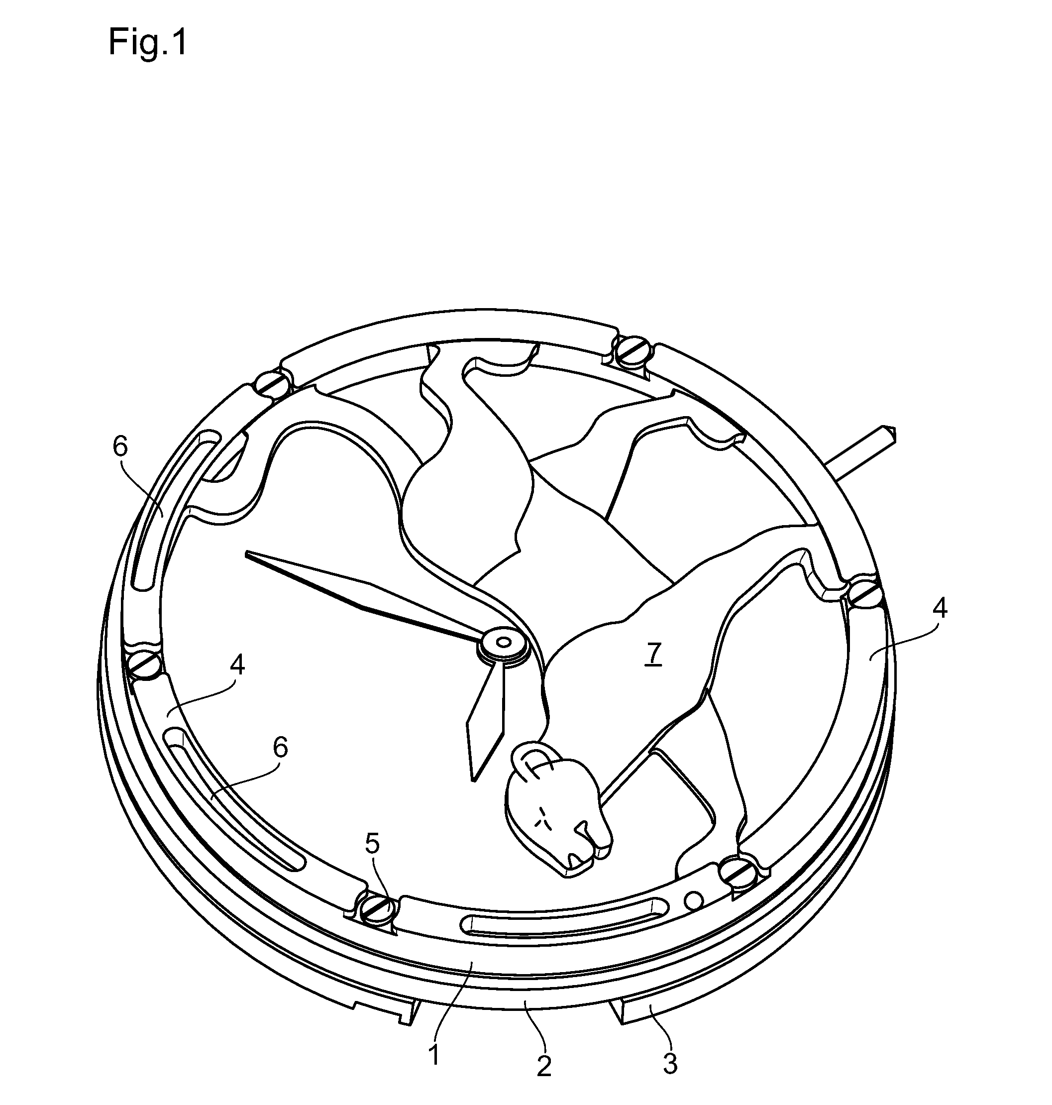
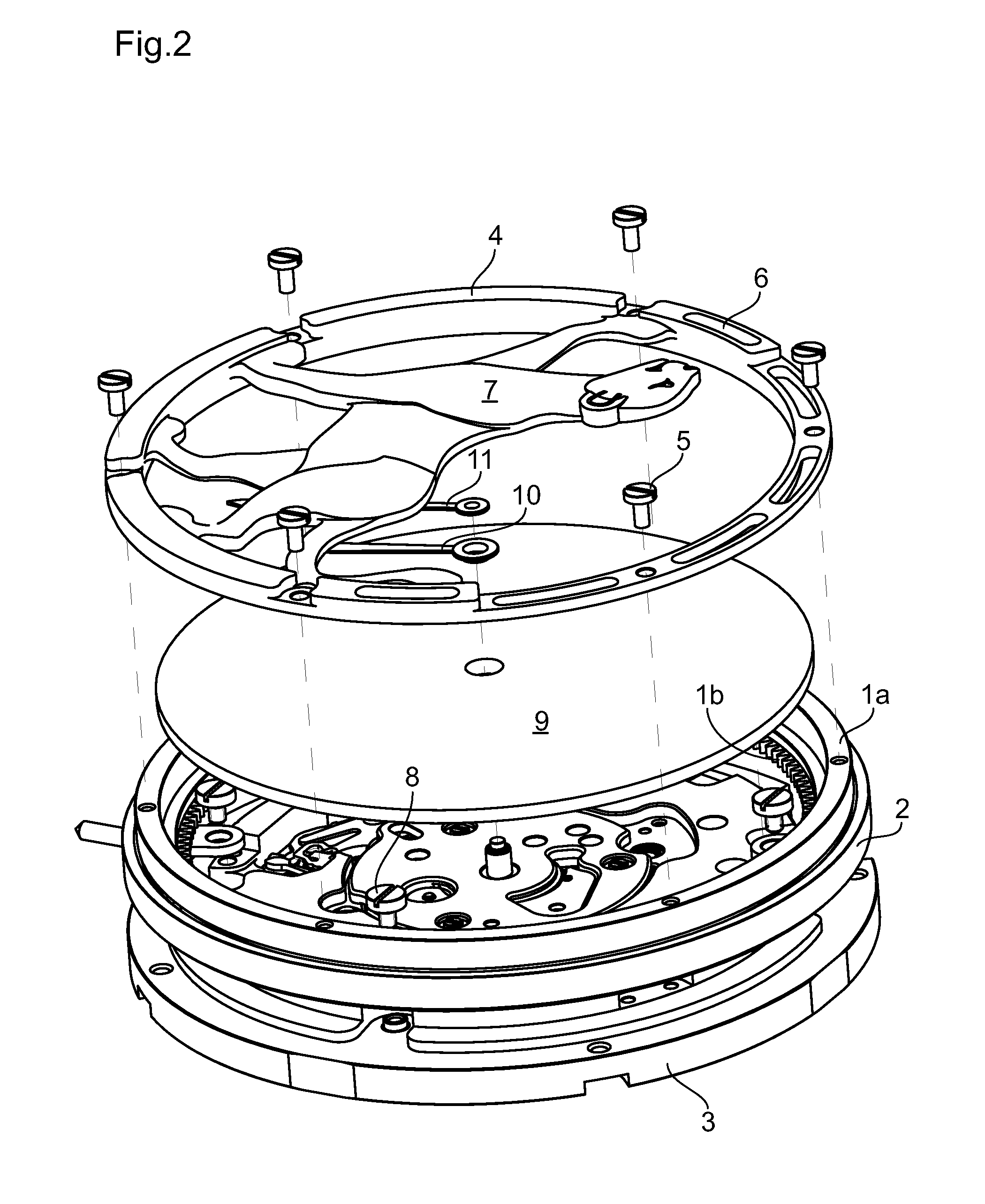
[0015]This oscillating mass has an annular mount 4 intended to be fixed by screws 5 to the upper part of the inner frame 1 of a ball bearing. In the illustrated embodiment (as can be seen particularly clearly in FIG. 2), the annular mount 4 has a thicker (and thus heavier) part and a thinner (and thus lighter) part and it is also provided with openings 6 in and along the thinner and lighter part. In this manner, the weight of the annular mount 4 is not distributed uniformly and the annular mount thus has an unbalance. The effect of the unbalance can also be obtained by other means known to the person skilled in the art—for example by using materials of different weights for the heavier and lighter parts respectively (either instead of or in combination with the means described above).

[0016]This oscillating mass also has a central part 7 located mainly or even exclusively in the part of the surface delimited by the heavier part of the annular mount 4. This central part 7 is fixed at ...


PUM


Abstract

The oscillating mass able to be fixed to a frame (1) pivoted on the exterior of a timepiece movement has toothing kinematically connected to the ratchet of a barrel of the timepiece movement. This oscillating mass has, on the one hand, a mount (4) which is annular or is in the form of an annular sector and is able to be fixed to the frame (1) and, on the other hand, a central part (7) located mainly or exclusively in one half of the surface delimited by the mount (4).

Description

BACKGROUND OF THE INVENTION[0001]The present invention relates to pivoting or oscillating automatic winding masses pivoted on the exterior of a timepiece movement, as well as to automatic winding timepiece movements and timepieces fitted with such an oscillating or pivoting mass.DESCRIPTION OF THE RELATED ART[0002]An oscillating mass of this type is known from document DE 10 2009 005 690 which has a circular ring, the inner edge of which is provided with toothing intended to be kinematically connected to the ratchet of a barrel. The upper surface of this circular ring bears the winding mass itself which is in the form of a crown sector having an angular span of preferably 180°.[0003]Unless the height or diameter of a movement fitted with such an automatic winding mass pivoted on the exterior of the movement is considerably increased, the power and efficiency of the automatic winding system are low, the dimensions and thus the weight of the mass being greatly reduced.[0004]An oscilla...

Claims


Application Information

Patent Timeline
IPC IPC(8): G04B5/02G04B5/18
CPCG04B5/02G04B5/184
Inventor KASAPI, CAROLEDECHAUMONT, LAURENT
Owner CARTIER INT
Why Eureka
Try Eureka