
Method for preventing surge in a dynamic compressor using adaptive preventer control system and adaptive safety margin

a dynamic compressor and control system technology, applied in the direction of machine/engine, pump control, non-positive displacement fluid engine, etc., can solve the problem of increasing the amount of gas flow provided at the gas inlet, reducing the efficiency of the compressor, and dampening out the noisy signal. the effect of the surg

Active Publication Date: 2015-09-15
ENERGY CONTROL TECH
View PDF16 Cites 7 Cited by
  • Summary
  • Abstract
  • Description
  • Claims
  • Application Information

AI Technical Summary

Benefits of technology

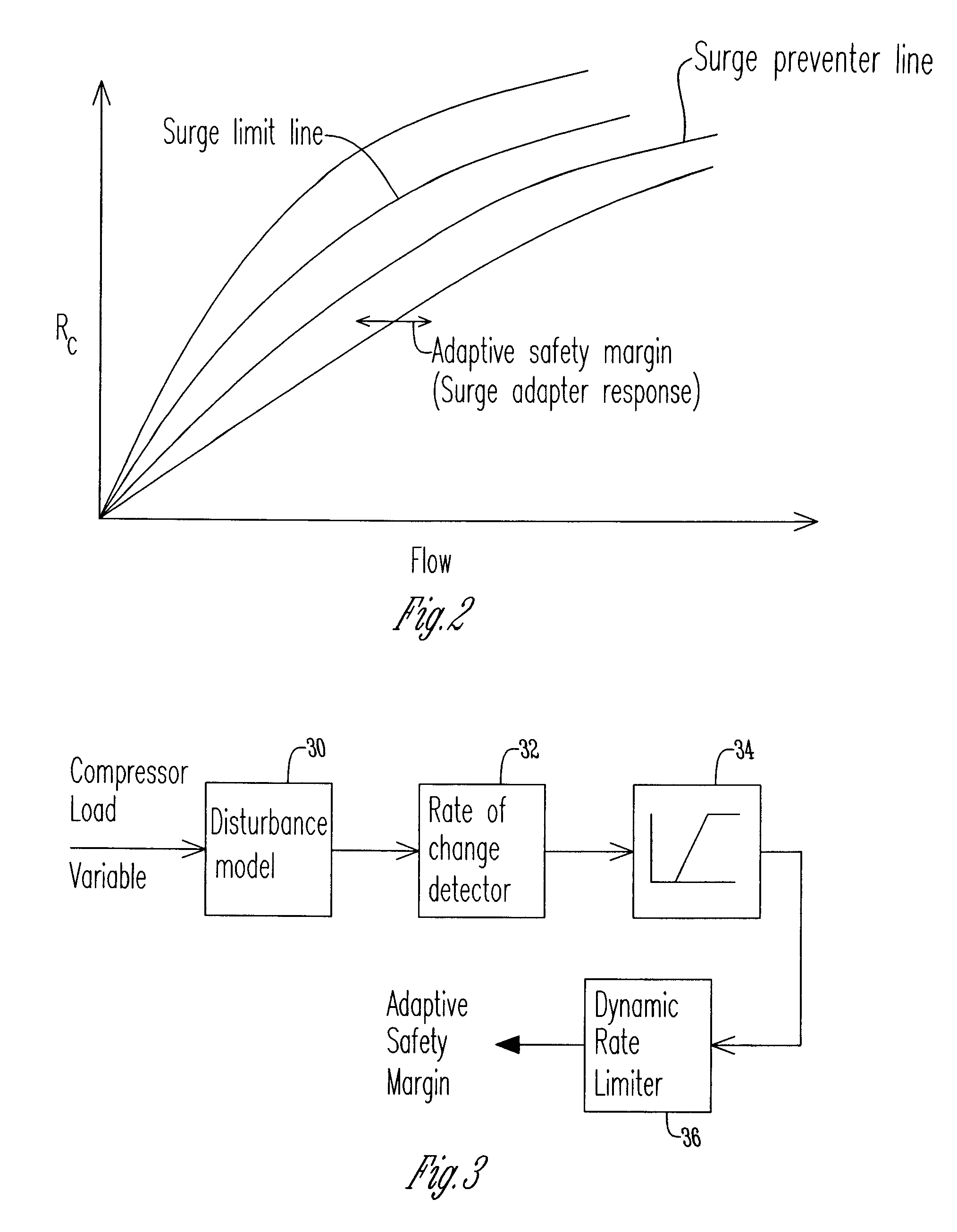
The patent describes a method for preventing surge in a dynamic compressor using a control system. The method involves sensing processed conditions to determine a compressor load variable, estimating a process disturbance model, and adjusting a safety margin using a rate limited or closed loop response. The opening of an anti-surge valve is then adjusted based on the safety margin and closed loop response. The technical effect of this patent is to provide a more effective and accurate method for preventing surge in dynamic compressors, which can improve operational efficiency and stability.

Problems solved by technology

A problem associated with dynamic compressors is the amount of gas flow that is provided at the gas inlet.
Specifically, if an insufficient amount of gas flow is provided, a surge within the system occurs causing damage to the compressor.
The problem with these control systems is that the rate of approach to surge is determined based on the derivative of a flow signal that is typically very noisy in field installations.
The control system dampens out the noisy signal through the use of passive digital filters rendering the variable set point determination ineffective and impractical in the field.
In addition, these control systems are very difficult to tune in the field because these techniques are not self adapting to varying process conditions.
Problems exist with this system because again, the set point is determined in a heuristic fashion.
The problem with open loop control response is that an open loop control response is difficult to set up in the field.
This renders the compressor system performance less than optimum.
A direct result of this is decrease in process efficiency, process instability, and even compressor damage from surge and process shutdown.
For control systems with closed loop fast response using variable gain method, it is very difficult to establish the control loop tuning in the field.
In addition, this method can make the control system ineffective or even unstable.
For control systems that use derivative based open loop control response the challenges come from noisy flow signals used to characterize response.
In these systems the control system dampens out noisy signals through the use of passive digital filters thus rendering the open loop derivative response determination ineffective and impractical to tune in the field.
Control systems based on closed loop rate limiting of the surge variable such as U.S. Pat. No. 5,798,941 suffer from the aspect of using a noisy derivative of flow signal as a process variable to determine quick valve opening.
In addition, another problem is that establishing the rate set point for optimum control response is very difficult for a field engineer.
Further, tuning a prior art control system in the field also is extremely challenging because the known prior art techniques are not self adapting to changes in field conditions and instead require high level of expertise in the field.

Method used


Image

  • Method for preventing surge in a dynamic compressor using adaptive preventer control system and adaptive safety margin
  • Method for preventing surge in a dynamic compressor using adaptive preventer control system and adaptive safety margin
  • Method for preventing surge in a dynamic compressor using adaptive preventer control system and adaptive safety margin

Examples


Embodiment Construction

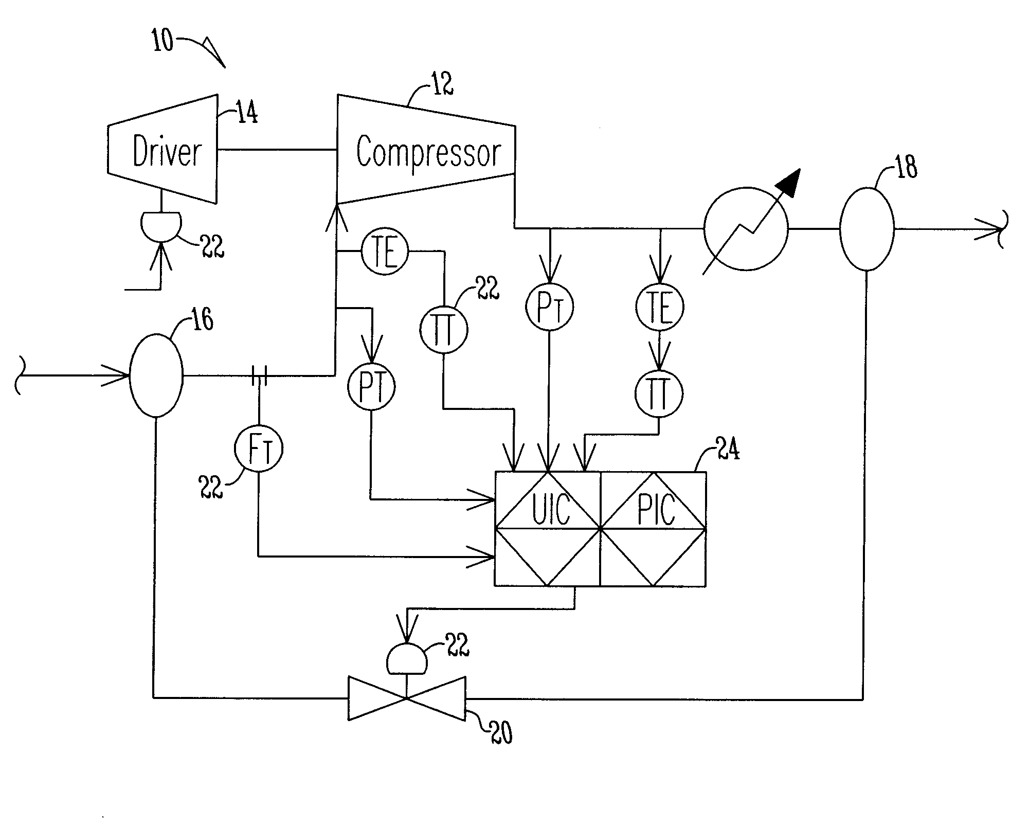
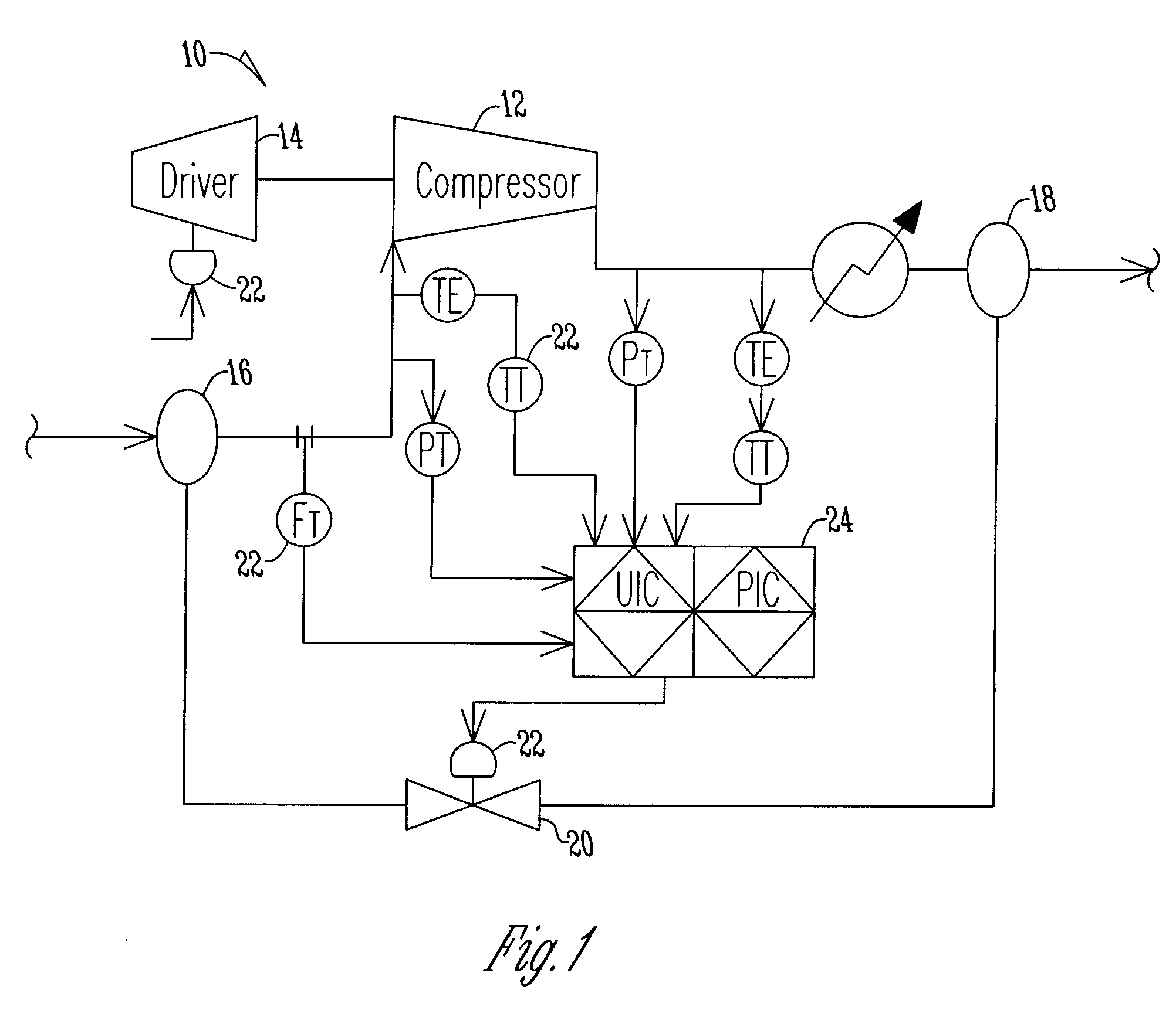
[0022]FIG. 1 shows a dynamic compressor 10 that includes a compressor 12 that is driven by a compressor driver 14. The compressor driver is of any type including a motor, gas turbine, steam turbine or the like. The compressor 12 has a gas inlet 16 and a gas outlet 18 wherein gas flows through the compressor 12 to be compressed. A surge or recycle valve 20 is fluidly connected between the gas inlet 16 and gas outlet 18 so that when the surge valve 20 opens a fluid flow path exists to convey gas from the gas outlet 18 to the gas inlet 16. A plurality of sensors 22 including pressure sensors, temperature sensors, flow measurement sensors and the like are placed throughout the dynamic compressor 10 in order to determine processed conditions for the components of the dynamic compressor including the compressor 12, the driver 14, the gas inlet 16, and gas outlet 18 and the surge valve 20. The plurality of sensors 22 are electrically connected to the control system 24 where the control sys...


PUM


Abstract

A method of preventing surge in a dynamic compressor is disclosed. The method includes providing an anti-surge valve having an adjustable opening for increasing the flow through a dynamic compressor. The next step is sensing process conditions in the dynamic control to determine a compressor load variable. A control system estimates a process disturbance model using the compressor load variable. The control system then adjusts a safety margin using a rate limited response and initiates a closed loop response using process feedback based on the process disturbance model. The control system adjusts the opening of the anti-surge valve according to the safety margin and closed loop response.

Description

BACKGROUND OF THE INVENTION[0001]The present invention is directed toward dynamic compressors. More specifically, the present invention is directed toward a method utilized by a control system within a dynamic compressor in order to provide surge protection for the dynamic compressor.[0002]A typical dynamic compressor has a gas inlet and a gas outlet wherein the compressor is driven by a compressor driver so that the gas, while flowing through the compressor, is compressed. A problem associated with dynamic compressors is the amount of gas flow that is provided at the gas inlet. Specifically, if an insufficient amount of gas flow is provided, a surge within the system occurs causing damage to the compressor. Because of the high price of compressors great care must be taken to ensure that compressors are not damaged.[0003]To minimize damage to compressors as a result of lack of gas flow at the inlet, a recycle or surge control valve is installed around dynamic compressors where the s...

Claims


Application Information

Patent Timeline
Patent Type & Authority Patents(United States)
IPC IPC(8): F04D27/02F04D27/00
CPCF04D27/001F04D27/0223
Inventor NARAYANAN, KRISHNANREINKE, PAULDUKLE, NIKHIL
Owner ENERGY CONTROL TECH
Learn More