
Drinking container with a drinking vessel and a drinking cap

a drinking container and drinking cap technology, applied in the direction of drinking vessels, packaging, closures, etc., can solve the problem of insufficient ventilation and achieve the effect of reducing the capillary action

Active Publication Date: 2015-09-01
MAPA
View PDF3 Cites 3 Cited by
  • Summary
  • Abstract
  • Description
  • Claims
  • Application Information

AI Technical Summary

Benefits of technology

The invention is a drinking vessel with a sealing cap and ventilation channel that prevents liquid from leaking through the vessel. The ventilation channel has a small cross-sectional surface area, allowing for sufficient ventilation without hindering the escape of liquid. The design of the channel prevents the channel from being compressed during tightening of the cap and the vessel. The bottom side of the open edge or the bottleneck of the vessel consists of a rigid material to ensure sufficient ventilation. The ventilation channel ensures liquid tightness and prevents liquid from flowing or dripping out of the vessel, even when the bottom is stepped on. The carrying region between neighboring channel sections is protected from damage due to tightening of the cap. The bottom side of the open edge and the top side of the opening edge have a roughness that prevents capillary action and a wetting with liquid, even in the presence of dishwashing liquid residue. This roughness is created through injection molding and later polishing of the tools.

Problems solved by technology

The design of the ventilation channel in the bottom side of the ring flange or in the top side of the opening edge, which consists of a rigid material, prevents a compression of the ventilation channel during tightening of the threaded ring to an extent that the ventilation channel is mainly pressed together and sufficient ventilation is no longer possible.
Dishwashing liquid residue can however result in wetting.

Method used


Image

  • Drinking container with a drinking vessel and a drinking cap
  • Drinking container with a drinking vessel and a drinking cap
  • Drinking container with a drinking vessel and a drinking cap

Examples


Embodiment Construction

[0063]While this invention may be embodied in many different forms, there are described in detail herein a specific preferred embodiment of the invention. This description is an exemplification of the principles of the invention and is not intended to limit the invention to the particular embodiment illustrated

[0064]In the present patent application, the terms “top” and “bottom” refer to the orientation of the drinking container, in which the drinking vessel is arranged on the bottom and the drinking cap on the top.

[0065]Furthermore, in the case of the following explanation of different exemplary embodiments, the same parts are provided with corresponding reference numbers.

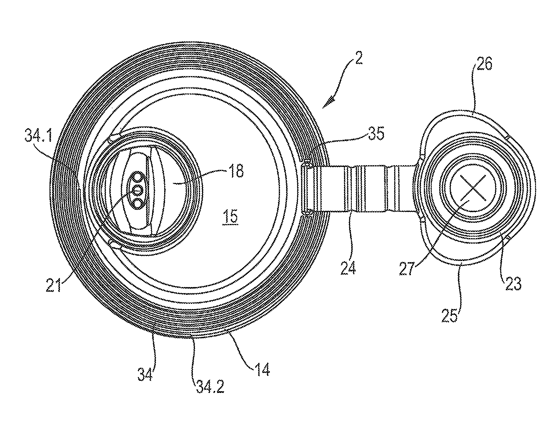
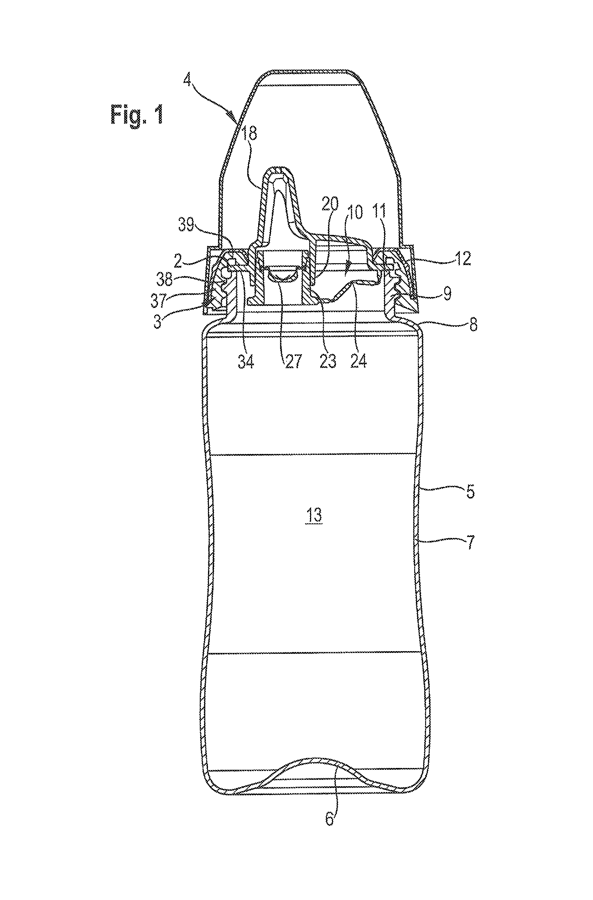
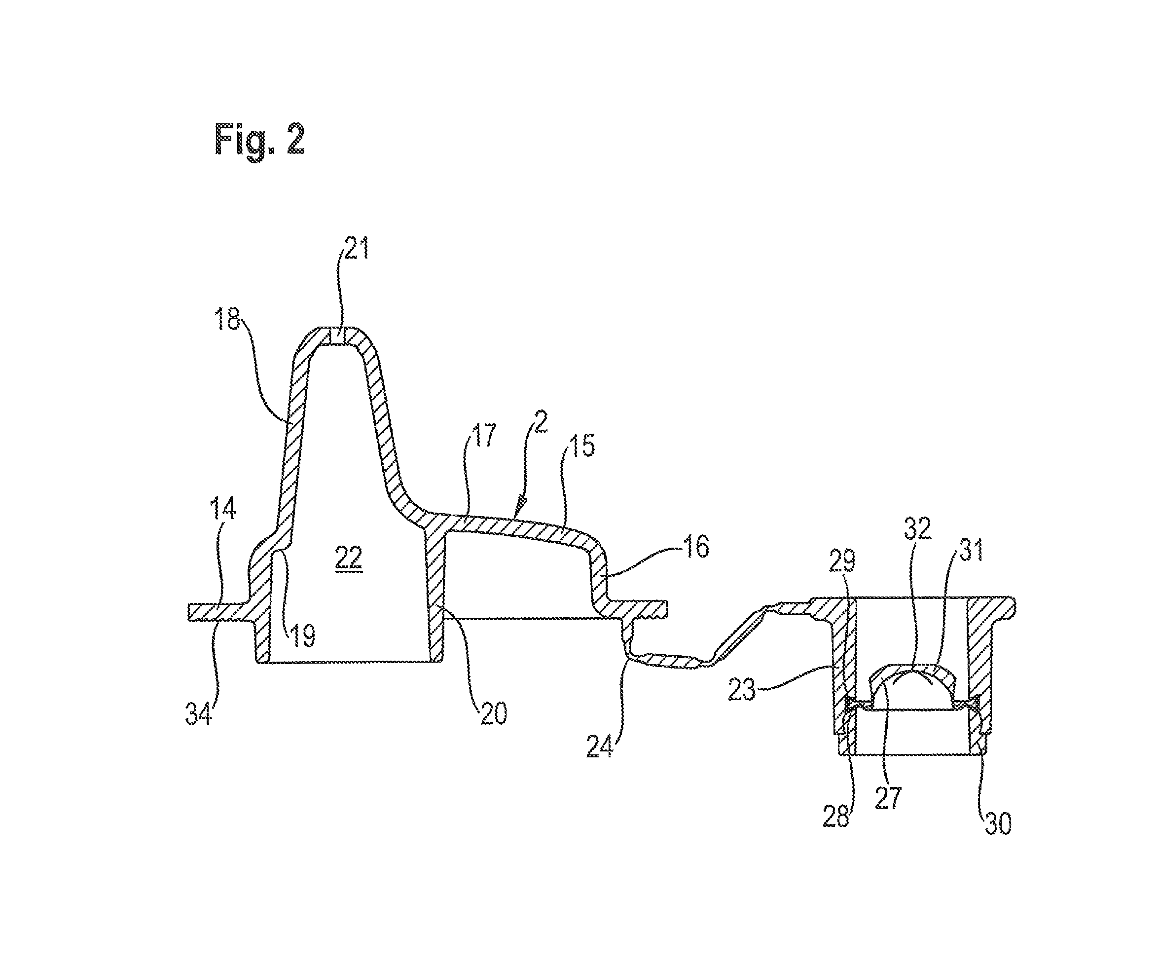
[0066]The drinking container in FIG. 1 has a drinking vessel 1 in the form of a drinking bottle, a drinking cap 2 in the form of a hard drinking spout, a threaded ring 3 and a closing cap 4.

[0067]The drinking vessel 1 has an elongated bottle body 5 with a bottle bottom 6 and a sleeve-like bottle side wall 7. On th...


PUM


Abstract

A drinking container with a drinking vessel, a drinking cap and a threaded ring. The drinking vessel has an inner space, a circular vessel opening, an opening edge surrounding the vessel opening and an external thread next to the vessel opening. The drinking cap has a bottom wall, a ring flange surrounding the bottom wall for abutment on the opening edge of the drinking vessel, a drinking element protruding outwards from the bottom wall and a valve for sealing and opening a passage from the inner space to the outside of the mouthpiece, which is openable for drinking and otherwise closable. A ventilation channel is present in the bottom side of the ring flange or in the top side of the opening edge.

Description

CROSS-REFERENCE TO RELATED APPLICATIONS[0001]This Utility Patent Application claims priority to DE 10 2013 010 431.9, filed on Jun. 24, 2013, the entire contents of which is incorporated herein by reference.STATEMENT REGARDING FEDERALLY SPONSORED RESEARCH[0002]Not applicable.BACKGROUND OF THE INVENTION[0003]The invention relates to a drinking container with a drinking vessel and a drinking cap. The drinking vessel is preferably a drinking bottle or a drinking cup and the drinking cap is preferably a drinking spout, a push / pull drinking cap, a drinking straw drinking cap or a drinking suction nozzle.[0004]Drinking caps have a bottom wall, a ring flange surrounding the bottom wall for fastening on the opening edge of the drinking vessel by means of a fastening ring and a mouthpiece protruding outward from the bottom wall with at least one drinking opening on the outside. The drinking opening is connected with the inside of the mouthpiece via a passage. By sucking on the mouthpiece dur...

Claims


Application Information

Patent Timeline
Patent Type & Authority Patents(United States)
IPC IPC(8): B65D47/24B65D51/16A61J9/04A47G19/22
CPCB65D47/248A47G19/2272A61J9/04B65D51/1611
Inventor LOHN, JURGEN
Owner MAPA
Learn More