
Gas burner

a burner and gas technology, applied in the field of gas burners, can solve the problems of gas burners, backfire drawbacks, and damage to components, and achieve the effects of preventing flame propagation, preventing flame propagation, and being easy to perform by the end user

Active Publication Date: 2015-08-25
SABAF SPA
View PDF8 Cites 5 Cited by
  • Summary
  • Abstract
  • Description
  • Claims
  • Application Information

AI Technical Summary

Benefits of technology

[0015]The gas burner for domestic use, according to the present invention, comprises at least one fuel gas injector facing the intake section of a corresponding Venturi effect mixer, one or more passages for the transit of primary air from above the supporting surface (preferably a hob), to which the burner is fixed, through to the above-mentioned Venturi effect mixer intake section, and means for preventing flame propagation of the fluid flow splitting type, interposed between the above-mentioned injector and the intake section of the corresponding Venturi effect mixer.
[0017]The use of a helically wound filiform element, naturally with calibrated coil pitch preferably between 0.3 and 1.2 mm, to produce the tubular body for preventing the passage of the flame, is advantageous both in terms of realisation, due to the relative simplicity of production of such component, and in terms of assembly, given the considerable dimensional adaptability thereof.
[0018]Furthermore, in the case of use of a helical spring, or if the helically wound filiform element is a wire made for example of spring steel or stainless spring steel, the elastic characteristic of said spring permits easy assembly and adaptation thereof in the gas burner, as an effective means for preventing flame propagation.
[0019]The use of a helical spring as a means for preventing flame propagation, interposed between injector and intake section of the relative Venturi effect mixer, is also particularly advantageous if the injector has to be replaced, for example to adapt the burner to a different type of fuel gas, or if the injector and adjacent chamber have to be cleaned, given that disassembly and subsequent assembly of said helical spring is extremely simple and can be easily performed by the end user.
[0020]It should be noted that, as the Applicant has verified in practice, the use of means for preventing flame propagation consisting of a tubular body made of a helically wound filiform element, in particular in a burner provided with a mixer consisting of an axial Venturi tube and with the use of mains (town) gas (e.g. G110 at 8 mbar), has proved to be extremely effective in preventing flame propagation inside the burner at the level of the mains (town) gas injector and relative Venturi tube.

Problems solved by technology

Gas burners for domestic use provided with primary air suction intakes from above the hob, in particular if provided with axial Venturi effect mixers (i.e. the classic Venturi tubes with convergent-divergent section), can suffer from the drawback of backfire, i.e. the fact that the flame, following the passages of the primary air or fuel mixture, tends to spread also inside the burner, and can reach the Venturi effect mixer and / or the relative fuel gas injector nozzle.
In particular, if at least one primary air intake is located, as is often the case with modern burners, near the igniter or pilot flames, at ignition the flame can easily spread inside the primary air passages until it laps the injector and the Venturi effect mixer inside the burner, with consequent damage to said components.
Although effective in preventing backfire propagation, this solution is onerous and not simple to produce, in addition to involving fairly complex assembly of the various burner components.
In fact, on the one hand the production of a wire net cage having a very fine mesh, and limited construction tolerances, is onerous and technologically complex, and on the other hand assembly of the cage with the burner components, and in particular the need to fit the cage on the injector and to fix it, for example by means of crimping, at the Venturi effect mixer intake section, is a difficult and awkward operation.

Method used


Image

  • Gas burner
  • Gas burner
  • Gas burner

Examples


Embodiment Construction

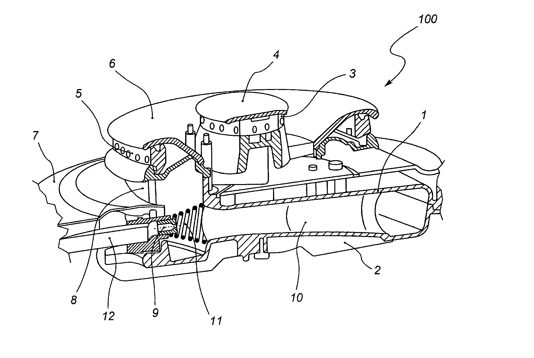
[0029]With reference first to FIG. 1, the gas burner 100 for domestic use illustrated herein, in particular suitable for cooking, according to the known technique, comprises a cup 2 on which the body 1 of the burner is mounted, which in turn is provided with one or more flame spreaders 3, 5 with relative covers 4, 6. The cup 2, designed to be fixed to a supporting surface 7, constituting the hob, is provided with at least one injector 9 which, connected to a relative inflow duct 12 of a fuel gas, faces the intake section of a corresponding Venturi effect mixer 10, with which the burner 100 is also provided.

[0030]In particular, as can be seen also in FIG. 2, the Venturi effect mixer, which according to a particular embodiment of the present invention can be an axial Venturi tube 10 (convergent-divergent), arranged for example along a horizontal axis or an axis slightly inclined downwards, can be obtained partly in the cup 2 and partly in the body 1 of the burner, so that said Venturi...


PUM


Abstract

Gas burner, preferably for domestic use, of the type comprising at least one fuel gas injector and at least one corresponding Venturi effect mixer, wherein the above-mentioned injector faces the intake section of said Venturi effect mixer, and one or more passages for the transit of primary air from above the supporting surface, to which the burner is fixed, to the intake section of the Venturi effect mixer. The burner is also provided with means for preventing flame propagation, of the fluid flow splitting type, which comprises at least one substantially tubular body, with relative lateral walls extending at least between the injector and the intake section of the Venturi effect mixer, advantageously consisting of at least one helically wound filiform element.

Description

CROSS-REFERENCE TO RELATED APPLICATION[0001]This application is a 371 of PCT / IT2010 / 000290, filed Jun. 30, 2010, the contents of which are incorporated herein by reference.FIELD OF THE INVENTION[0002]The present invention concerns a gas burner, preferably for domestic use, of the type comprising at least one injector for a fuel gas, and in particular mains gas (or “town gas”), at least one corresponding Venturi effect mixer, the intake section of which is positioned facing the injector, and one or more passages for the transit of primary air from above the hob to which the burner is fixed, through to the above-mentioned intake section of the Venturi effect mixer.BACKGROUND ART[0003]Gas burners for domestic use provided with primary air suction intakes from above the hob, in particular if provided with axial Venturi effect mixers (i.e. the classic Venturi tubes with convergent-divergent section), can suffer from the drawback of backfire, i.e. the fact that the flame, following the pa...

Claims


Application Information

Patent Timeline
Patent Type & Authority Patents(United States)
IPC IPC(8): F23D14/82F23D14/06F23D14/64
CPCF23D14/82F23D14/065F23D14/64F23D2900/14062
Inventor BETTINZOLI, ANGELO
Owner SABAF SPA
Learn More