Stand for supporting portable electronic display device

a technology for electronic display devices and stands, applied in the direction of machine supports, instruments, manufacturing tools, etc., can solve the problems of manual dexterity and create discomfort for users, and achieve the effect of facilitating rapid change of modes

Inactive Publication Date: 2015-08-25
FLOTSAM HK
View PDF15 Cites 0 Cited by
  • Summary
  • Abstract
  • Description
  • Claims
  • Application Information

AI Technical Summary

Benefits of technology

[0041]In still further aspects, the base of the stand may be sewn with a non-slip piping or similar protrusion along the seam to assist with grip on the base on smooth surfaces.
[0042]The base may include a carry handle incorporated to the top surface to assist in portability.
[0045]The soft fabric base may be interfaced with a rubber or silicone shelf component design and used to fully support tablet computing devices in landscape or portrait format, from a horizontal to a near vertical angle of operation, whilst providing quick device re-orientation and angular incline adjustments on a self levelling base on a variety of surfaces and at various locations. The stand may include a shelf component made from rubber, silicone or materials with similar mechanical function and anti slip characteristics, affixed to the soft fabric base. The shelf component may provide resting support and grip for the personal electronic display device in operation either in landscape or portrait format.
[0046]Advantageously, as the stand does not require a securing mechanism to secure the personal electronic display device, it facilitates rapid change in mode from landscape to portrait format.

Problems solved by technology

During extended use in various locations which are not specifically configured for operation of display devices can create discomfort for the user.
Whilst current commercially available stands provide a variety of manners to support personal electronic devices for operation by the user, these stands typically require a flat, hard surface to rest upon and adjustment can be cumbersome and often requires manual dexterity as these stands are often structurally and mechanically rigid and may include cumbersome adjustment mechanisms.

Method used


Image

  • Stand for supporting portable electronic display device
  • Stand for supporting portable electronic display device
  • Stand for supporting portable electronic display device

Examples


Embodiment Construction

[0076]The following description refers to preferred embodiments of a stand according to the present invention. To facilitate an understanding of the invention, reference is made in the description to the accompanying drawings whereby the stand is illustrated in preferred embodiments. Similar components between the embodiments are identified by the same reference numerals.

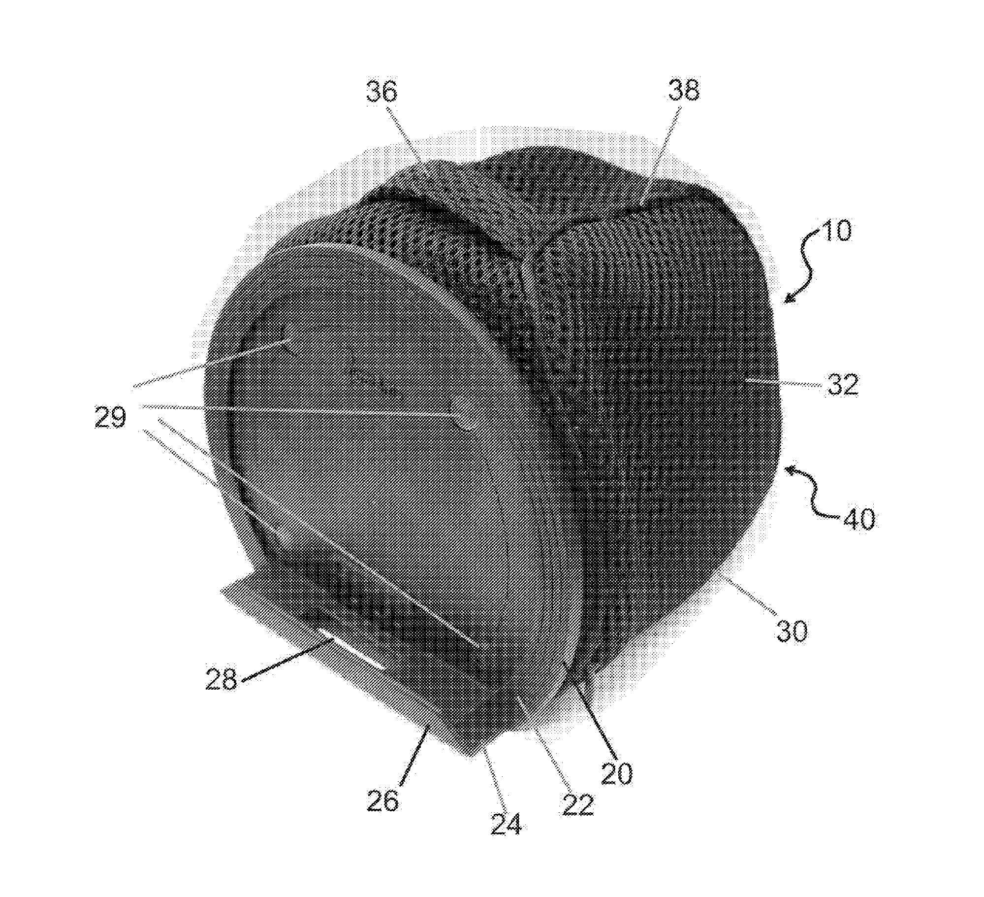
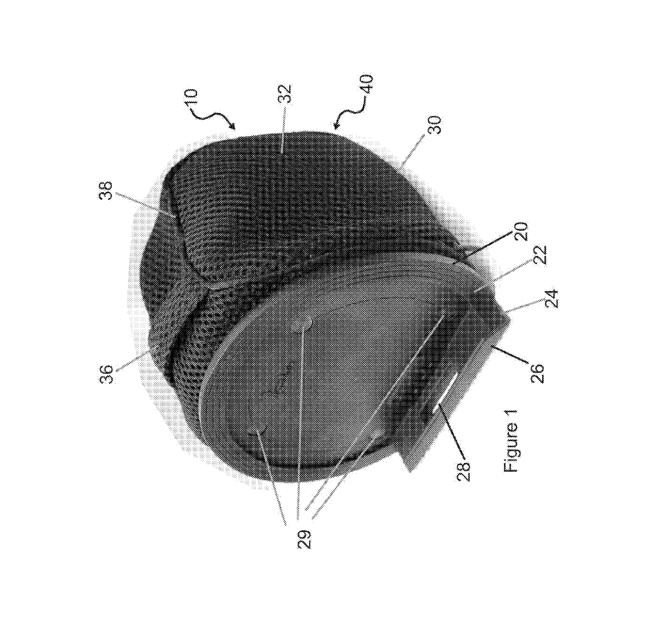
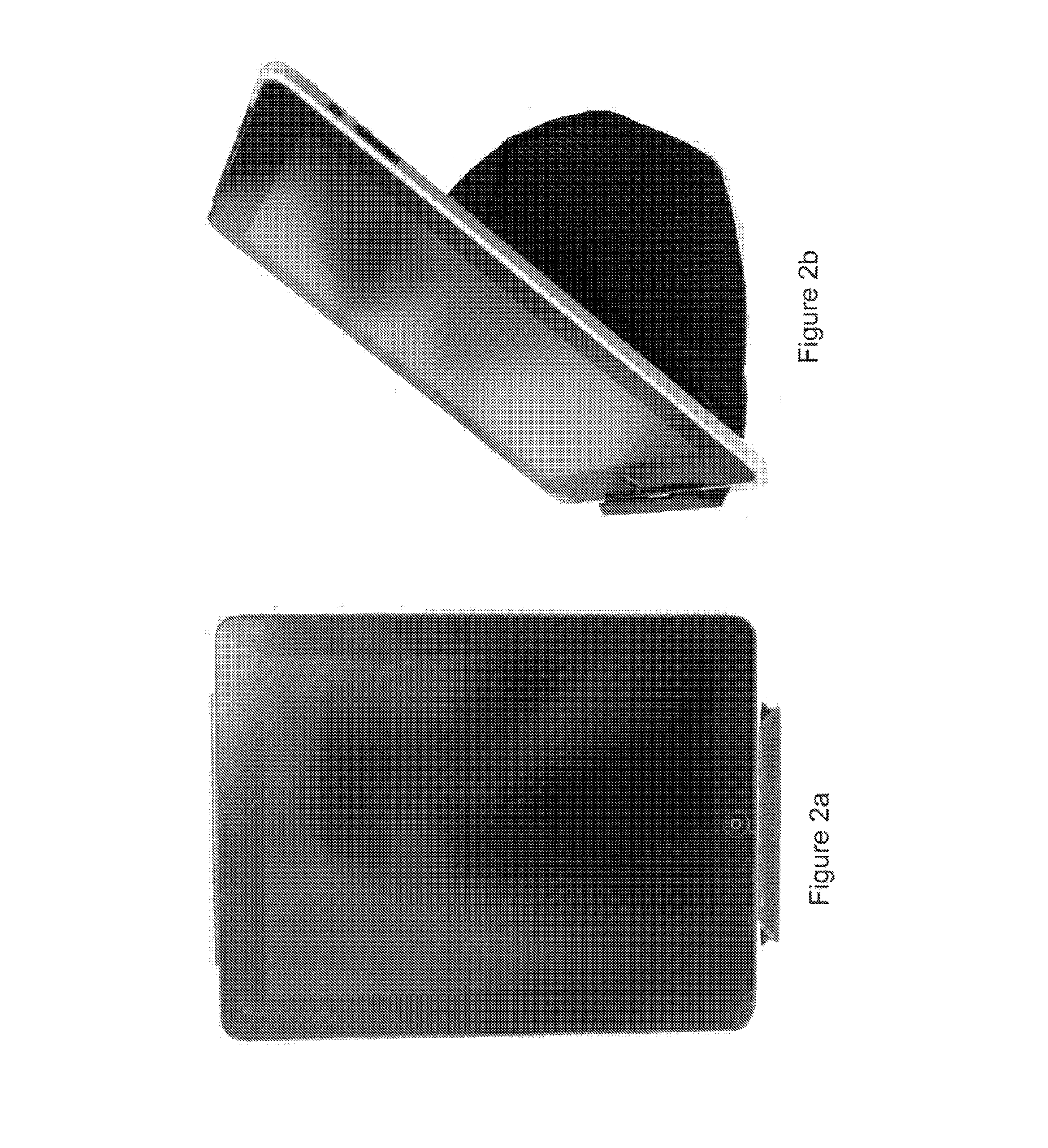
[0077]Referring to FIG. 1, FIGS. 2a-2d, FIG. 3a and FIG. 3b, an exemplary embodiment of a stand 10 of the present invention is depicted, the stand 10 comprises an engagement portion 20 and a support portion 30 for engagement and interaction with a support surface 40. The engagement portion 20 provides for engagement with a portable electronic display device as shown in FIG. 2.

[0078]The support portion 30 of the stand 10 includes a deformable mass 32 which is shown conforming substantially to a smooth support surface 40, and which allows for adjustment of the inclination of the portable electronic display device to a...


PUM

PropertyMeasurementUnit
inner volumeaaaaaaaaaa
forceaaaaaaaaaa
deformable massaaaaaaaaaa

Abstract

The present invention provides an electronic display device stand which enables adjustment to, support at and maintenance of, the orientation of a supported electronic display device. The stand preferably comprises an engagement portion which supports and engages the portable electronic display device; and a support portion which allows adjustability of the orientation and maintenance of the device at the desired user defined orientation. The support portion includes a deformable mass portion which can be deformed by a user, and maintains support of the display device at the user defined orientation.

Description

FIELD OF THE INVENTION[0001]This invention relates to portable electronic display devices, in particular to stands for supporting portable electronic display devices such as tablet computers, e-books and personal data display devices.BACKGROUND OF THE INVENTION[0002]Portable electronic computing devices such as laptop computers and personal tablet computers and other personal electronic display devices such as e-book readers, digital photo frames and personal games consoles provide for interaction with such computing devices at more than one location, such as in home or office locations, outdoor locations, public transport, hotels and the like[0003]Interaction with personal display devices may not be mediated with keyboards only, and may include stylus, mouse or operation through the user's fingers by way of a touch sensitive display screen on a the device.[0004]For operation of such devices, users may operate the device with one hand while supporting the weight of the device with t...

Claims


Application Information

Patent Timeline
Patent Type & Authority Patents(United States)
IPC IPC(8): F16M11/00G06F1/16
CPCF16M11/00G06F1/1632Y10T29/49826
Inventor LAU, TERENCE BOONKHENG
Owner FLOTSAM HK
Why Eureka
Try Eureka