
Image pickup lens

a technology of image pickup and lens, which is applied in the field of image pickup lenses, can solve the problems of reducing the size and thinning of the imaging devices built in the field, unable to recognize, and the value of the lens is approximately 3.0, so as to facilitate cost reduction and mass production

Active Publication Date: 2015-08-18
TOKYO VISIONARY OPTICS CO LTD
View PDF12 Cites 4 Cited by
  • Summary
  • Abstract
  • Description
  • Claims
  • Application Information

AI Technical Summary

Benefits of technology

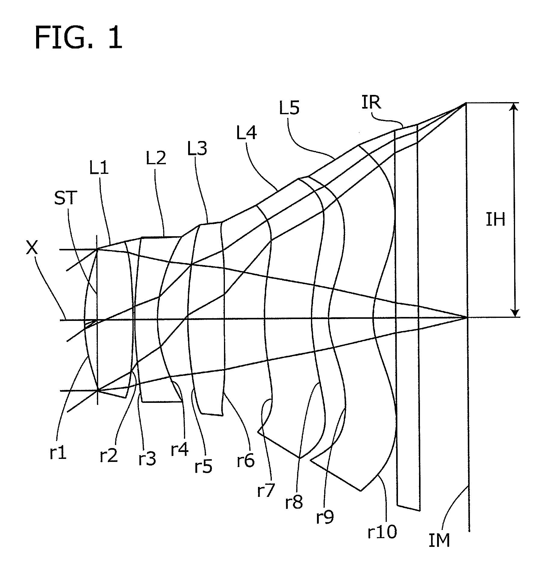
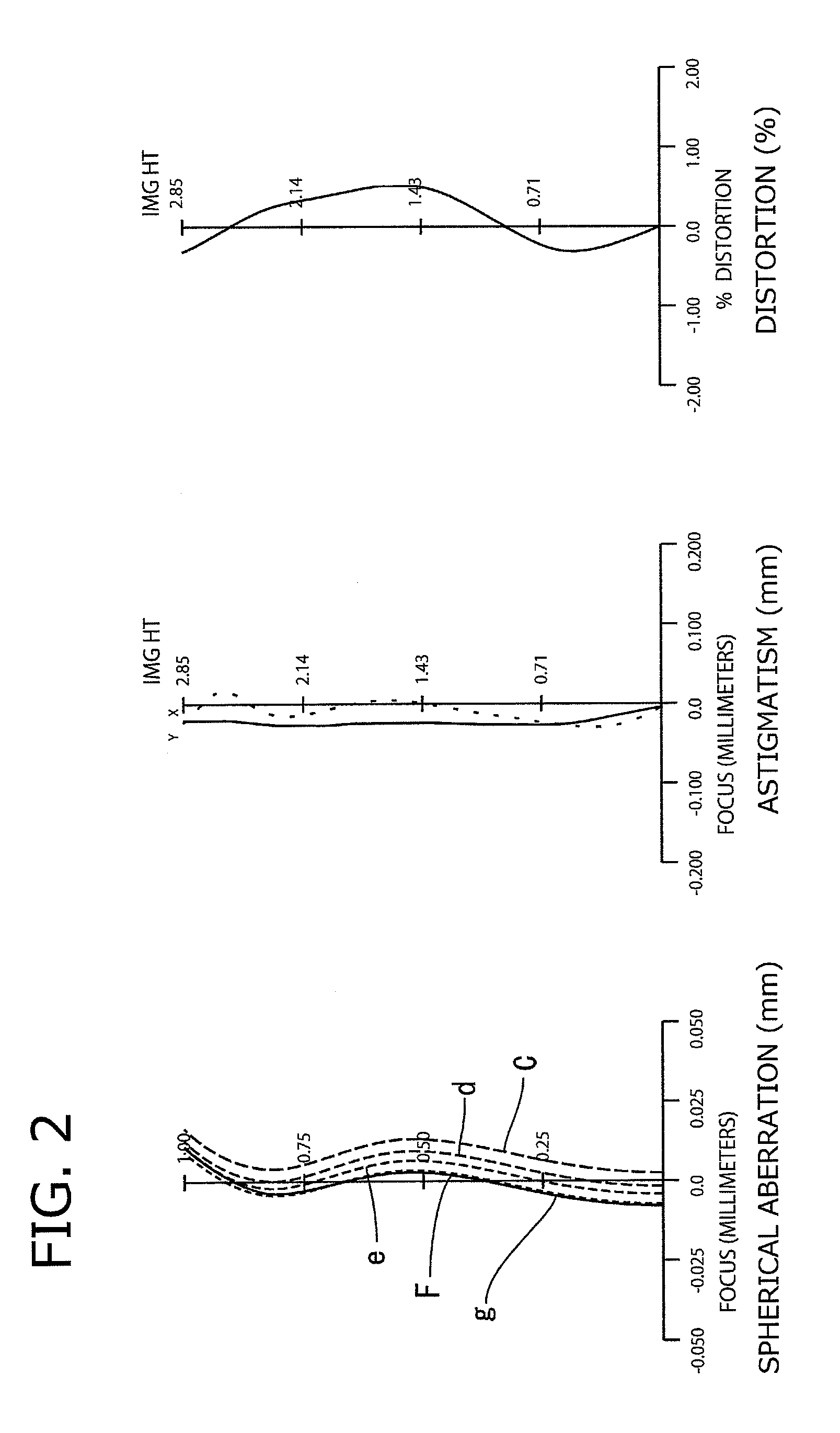
The present invention provides an image pickup lens that solves problems of prior art by achieving downsizing and thinning of a five-lens configuration, with small F-value, satisfactory aberration correction, wide angle of field, and cost reduction. The lens has three positive lenses and two negative lenses arranged in a specific configuration. The second lens is designed to have an aperture stop, ensuring satisfactory image-side telecentric property. The fourth and fifth lenses have concave surfaces facing the image side near the optical axis, allowing for satisfactory field curvature correction and improved telecentric properties. All lenses are formed of plastic materials, facilitating mass production and cost reduction.

Problems solved by technology

Along with the increasing demands for thinning of portable terminals for reasons such as user-friendliness and design, demands for downsizing and thinning of the imaging devices built therein are also becoming severe.
However, the F-value of the lenses is approximately 3.0, which cannot be recognized as ensuring a sufficient brightness for imaging elements having increased number of pixels.
As for the image pickup lens disclosed in Patent Document 2, it realizes a lens system having an F-value as bright as 2.05 to 2.5 and high aberration correction ability, but since the power of the first lens is weak, the configuration is disadvantageous for realizing a thinner lens.

Method used


Image

  • Image pickup lens
  • Image pickup lens
  • Image pickup lens

Examples


embodiment 1

[0074

[0075]Basic lens data will be shown in Table 1 below.

[0076]

TABLE 1Embodiment 1Unit mmf = 4.109Fno = 2.20ω = 34.89IH = 2.856Surface dataRefractiveindexAbbe numberSurface No. iCurvature radius rSurface distance dNdνd(Object surface)InfinityInfinityStopInfinity−0.171*2.14890.6451.53556.1602*−8.21490.0233*4.26620.3021.61425.5774*1.62360.40235*4.50970.48611.53556.1606*21.18520.53657*3.94260.63141.53556.1608*1.94220.22679*0.99750.59251.53556.16010* 1.07720.3511 Infinity0.31.51764.19812 Infinity0.6068Image PlaneInfinitySingle lens dataLensStart planeFocal length113.24023−4.4223510.55547−8.007596.973Aspheric dataFirst surfaceSecond surfaceThird surfaceFourth surfaceFifth surfacek0.000E+000.000E+000.000E+000.000E+000.000E+00A4−2.117E−021.812E−02−5.379E−02−1.095E−01−2.784E−02A6−4.623E−03−7.453E−029.387E−037.311E−021.933E−02A8−8.926E−033.686E−02−1.272E−02−6.365E−02−7.745E−03A10−9.320E−03−1.230E−021.637E−022.498E−02−3.340E−03A120.000E+000.000E+000.000E+000.000E+002.097E−03A140.000E+000.000...

embodiment 2

[0080

[0081]Basic lens data will be shown in Table 2 below.

[0082]

TABLE 2Embodiment 2Unit mmf = 4.132Fno = 2.05ω = 34.66IH = 2.856Surface dataRefractiveindexAbbe numberSurface No. iCurvature radius rSurface distance dNdνd(Object surface)InfinityInfinityStopInfinity−0.171*2.3170.7031.53556.1602*−6.4660.0233*4.39960.32161.61425.5774*1.64940.38645*5.0320.48581.53556.1606*20.3010.50997*3.750.64181.53556.1608*2.20430.2399*1.07610.61481.53556.16010* 1.12280.3111 Infinity0.31.51764.19812 Infinity0.6672Image PlaneInfinitySingle lens dataLensStart planeFocal length113.26923−4.4563512.32547−11.651598.607Aspheric dataFirst surfaceSecond surfaceThird surfaceFourth surfaceFifth surfacek0.000E+000.000E+000.000E+000.000E+000.000E+00A4−2.099E−022.086E−02−5.400E−02−1.133E−01−2.958E−02A6−4.167E−03−7.287E−028.212E−037.166E−022.067E−02A8−6.781E−033.669E−02−1.508E−02−6.390E−02−6.801E−03A10−6.771E−03−1.165E−021.249E−022.004E−02−3.312E−03A120.000E+000.000E+000.000E+000.000E+001.848E−03A140.000E+000.000E+000...

embodiment 3

[0085

[0086]Basic lens data will be shown in Table 3 below.

[0087]

TABLE 3Embodiment 3Unit mmf = 4.073Fno = 2.40ω = 35.07IH = 2.856Surface dataRefractiveindexAbbe numberSurface No. iCurvature radius rSurface distance dNdνd(Object surface)InfinityInfinityStopInfinity−0.131*2.174670.6021.53556.1602*−6.923850.02353*4.002540.28741.61425.5774*1.568020.3975*6.608490.42591.53556.1606*−197.9730.57037*3.73030.57531.53556.1608*2.56580.29259*1.13170.60421.53556.16010* 1.07320.3111 Infinity0.31.51764.19812 Infinity0.6559Image PlaneInfinitySingle lens dataLensStart planeFocal length113.15523−4.3563511.92047−18.5025914.828Aspheric dataFirst surfaceSecond surfaceThird surfaceFourth surfaceFifth surfacek0.000E+000.000E+000.000E+000.000E+000.000E+00A4−2.275E−022.199E−02−6.964E−02−1.369E−01−4.238E−02A6−5.843E−04−8.795E−021.447E−028.867E−021.425E−02A8−2.539E−025.423E−02−3.991E−03−7.082E−02−7.989E−03A10−1.798E−03−1.989E−021.284E−022.302E−022.170E−03A120.000E+000.000E+000.000E+000.000E+002.933E−03A140.000E...


PUM


Abstract

An image pickup lens includes a first lens having a positive refractive power with a convex surface facing the object side, a second lens having a negative refractive power with a concave surface facing the image side, a third lens having a positive refractive power with a convex surface facing the object side, a fourth lens having both sides formed as aspheric surfaces and having a negative refractive power with a concave surface facing the image side, and a fifth lens having both sides formed as aspheric surfaces and having a positive refractive power with a concave surface facing the image side, wherein the first lens and the second lens satisfy following conditional expressions (1), (2) and (3);45<ν1<90  (1)22<ν2<35  (2)2.0<ν1 / ν2 <2.6  (3)where ν1 represents an Abbe number of the first lens, and ν2 represents an Abbe number of the second lens.

Description

[0001]The present application is based on and claims priority of Japanese patent application No. 2012-084089 filed on Apr. 2, 2012, and Japanese patent application No. 2012-075628 filed on Mar. 29, 2012, the entire contents of which are hereby incorporated by reference.BACKGROUND OF THE INVENTION[0002]1. Field of the Invention[0003]The present invention relates to an image pickup lens for forming an image of an object on a solid imaging element such as a CCD sensor or a C-MOS sensor adopted in small-sized imaging devices. More specifically, the present invention relates to an image pickup lens composed of five lenses, which is built into an imaging device mounted on portable terminals such as cellular phones and smartphones, PDAs (Personal Digital Assistances), and game machines or information terminals such as personal computers and the like, where downsizing and thinning are pursued.[0004]2. Description of the Related Art[0005]Recently, the market of portable terminals having imag...

Claims


Application Information

Patent Timeline
Patent Type & Authority Patents(United States)
IPC IPC(8): G02B9/60G02B13/18G02B3/02G02B13/00
CPCG02B13/0045G02B9/60
Inventor HASHIMOTO, MASAYA
Owner TOKYO VISIONARY OPTICS CO LTD
Learn More