
Engine

a technology for engines and components, applied in the field of engines, can solve problems such as negative circumstances, and achieve the effects of large thermal load reduction, large thermal load reduction on the auxiliary engine component 6, and large thermal load reduction on the auxiliary engine component 6

Inactive Publication Date: 2015-08-04
KUBOTA CORP
View PDF17 Cites 4 Cited by
  • Summary
  • Abstract
  • Description
  • Claims
  • Application Information

AI Technical Summary

Benefits of technology

[0008]An advantage of the present invention is to provide an engine capable of easing a thermal load on an auxiliary engine component disposed adjacent to an exhaust pipe.
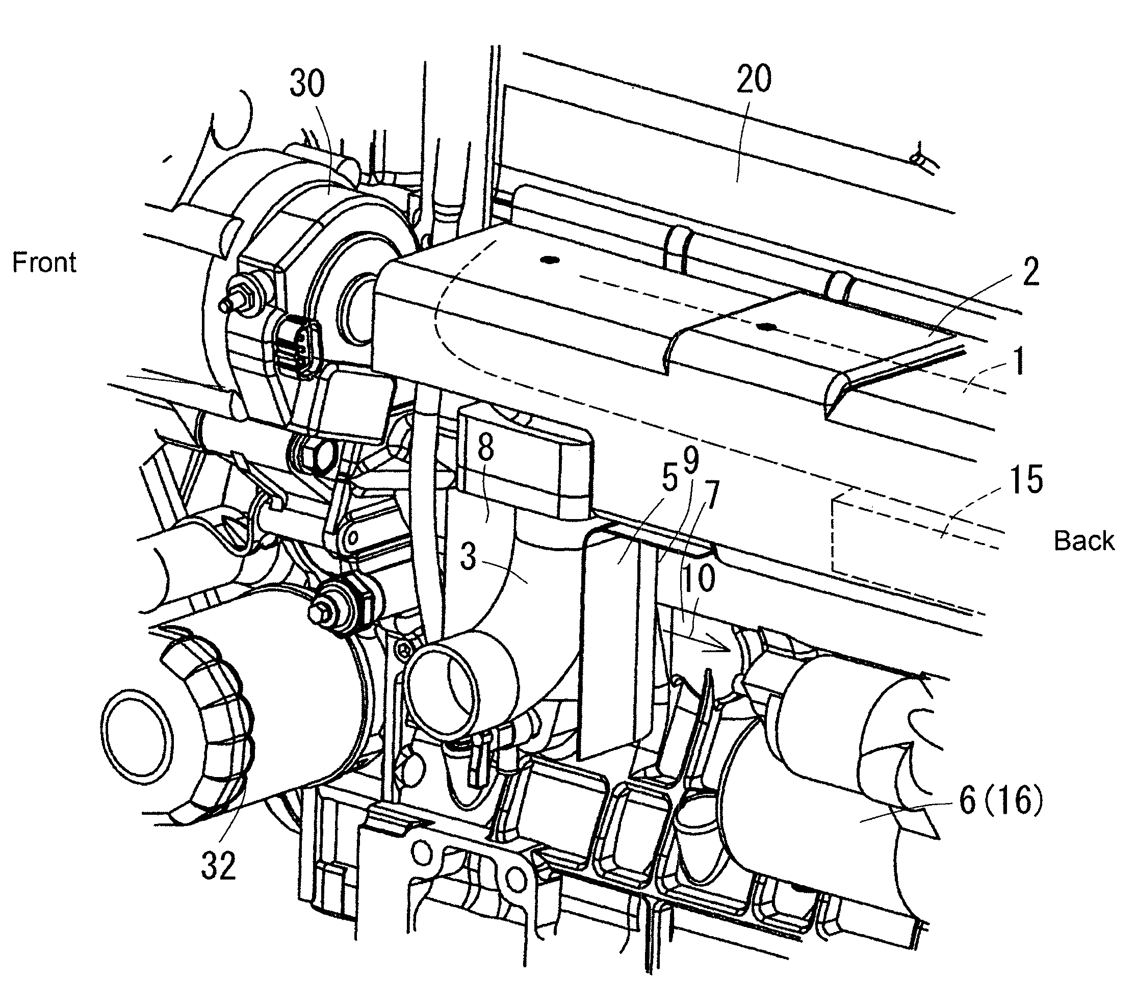
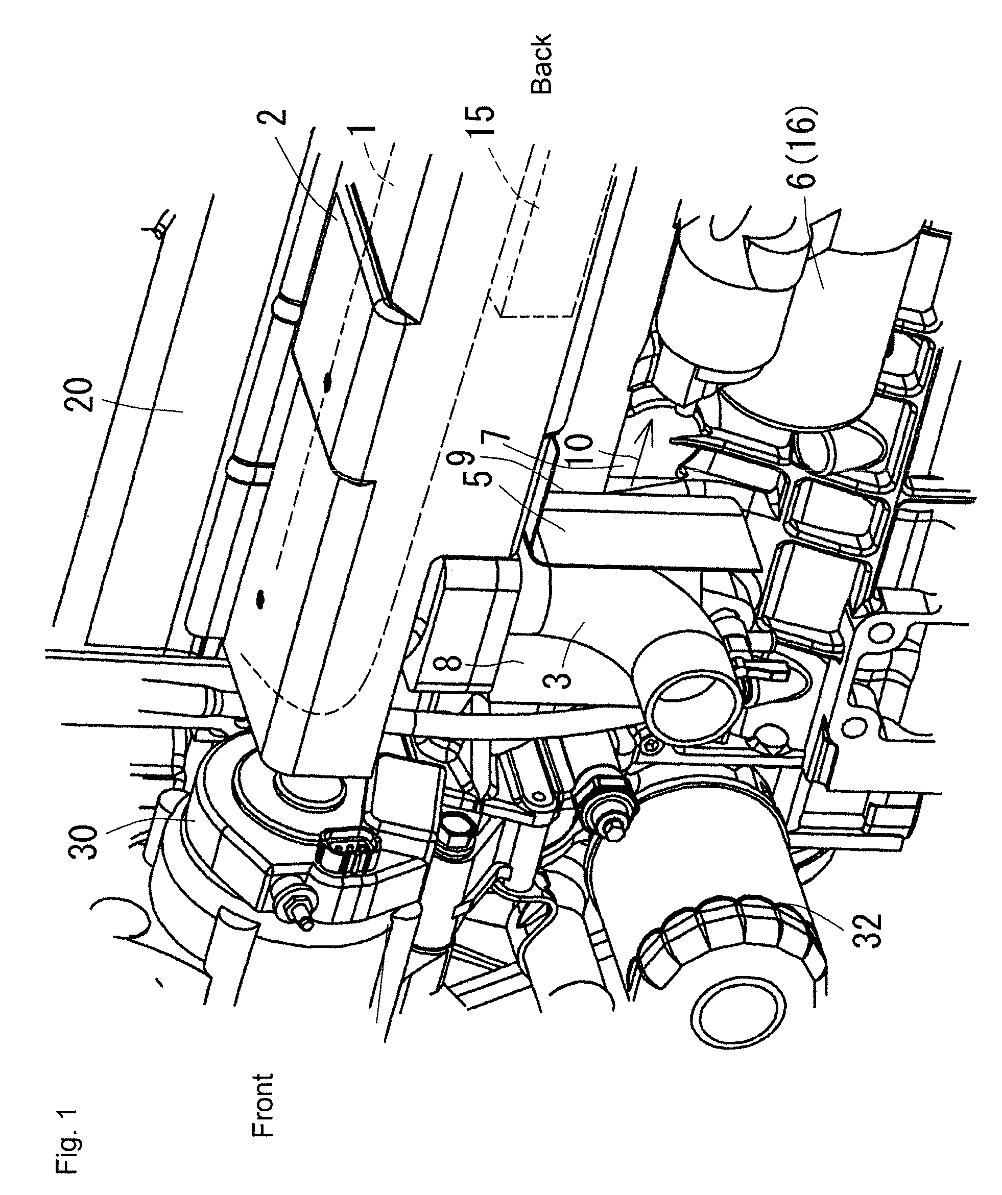
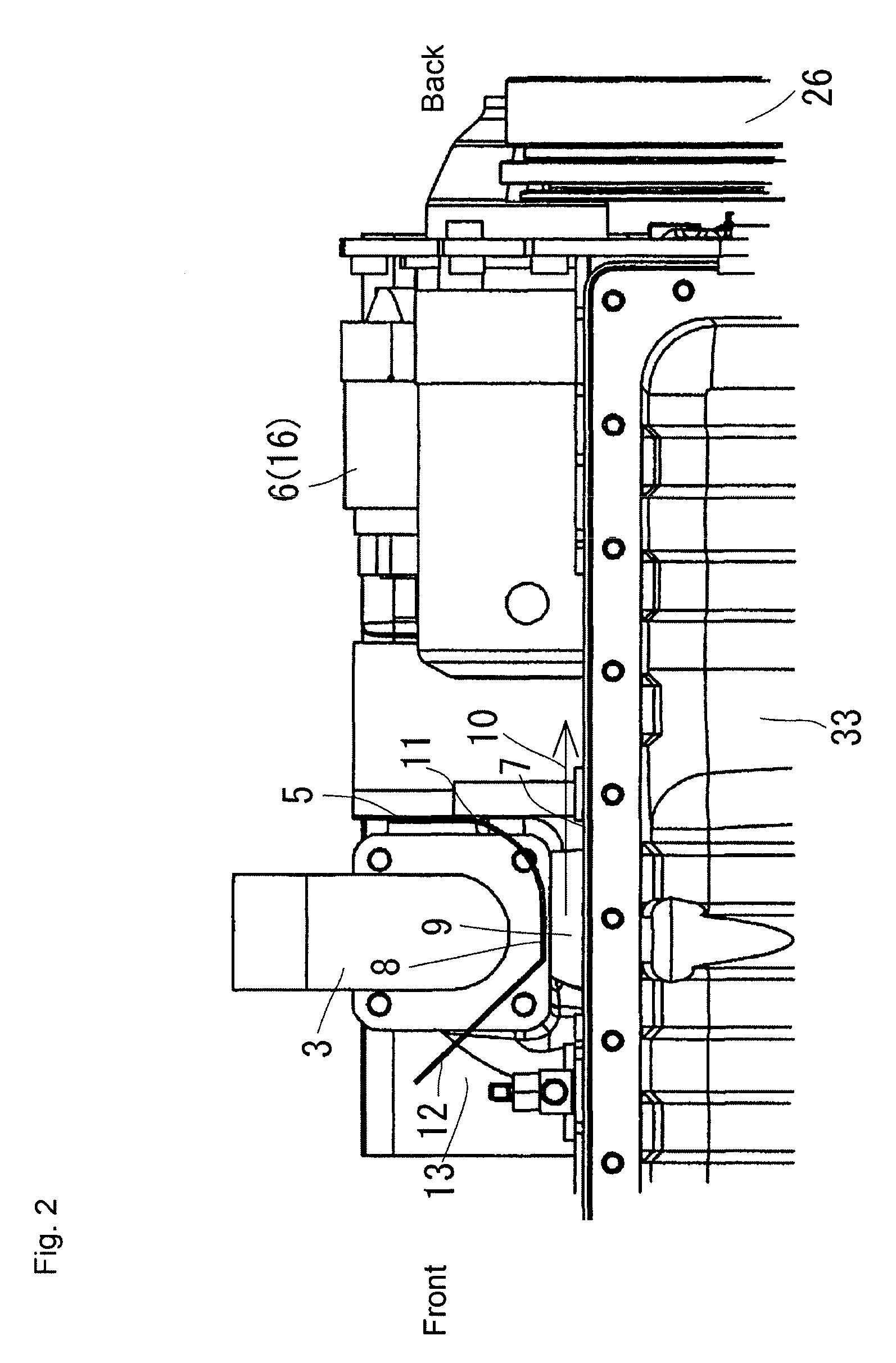
[0009]Characteristic elements of the invention are as follows. As exemplified in FIGS. 1 and 2, an exhaust manifold 1 is covered by a manifold heat shield cover 2 and an exhaust pipe 3 is directed downward from the exhaust manifold 1. In such an engine, as exemplified in FIG. 3, a cooling fan 4 is disposed on a front portion of the engine and the exhaust pipe 3 is positioned on the air flow path of the cooling fan 4. As exemplified in FIGS. 1 and 2, an auxiliary component heat shielding plate 5 is directed from the manifold heat shield cover 2 along a back side of the exhaust pipe 3. An auxiliary engine component 6 is disposed beneath the manifold heat shield cover 2 on a back side of the auxiliary component heat shielding plate 5. Between the exhaust pipe 3 and a cylinder block 7, an air flow guide plate 8 is positioned so as to provide an air flow space 9 between the air flow guide plate 8 and the cylinder block 7. A cooling air flow 10 passing through the air flow space 9 is thus supplied to the auxiliary engine component 6.
[0010]The invention achieves the following result. The thermal load on an auxiliary engine component disposed adjacent to the exhaust pipe may be eased. As exemplified in FIG. 1, the temperature of the exhaust pipe 3 is lowered by the cooling air flow 10, and in addition, the heat released from the exhaust pipe 3 to the auxiliary engine component 6 is blocked by the auxiliary component heat shielding plate 5. The heat released from the exhaust manifold 1 to the auxiliary engine component 6 is blocked by the manifold heat shield cover 2. Also, the auxiliary engine component 6 is air-cooled by the cooling air flow 10. Accordingly, the thermal load on the auxiliary engine component 6 disposed adjacent to the exhaust pipe 3 may be eased.
[0011]Further, the invention achieves the result that reduction of the thermal load on the auxiliary engine component 6 is large. As exemplified in FIG. 2, the air flow guide plate 8 is directed from the endmost portion 11 of the auxiliary component heat shielding plate 5 on the cylinder block 7 side along a peripheral wall of the exhaust pipe 3. The flow of heated exhaust air from the exhaust pipe 3 is thus interrupted by the auxiliary component heat shielding plate 5 and the air flow guide plate 8, and so does not flow into the auxiliary engine component 6 side. Reduction of the thermal load on the auxiliary engine component 6 is therefore large.
[0012]In addition, the invention achieves the result that reduction of the thermal load on the auxiliary engine component 6 is large. As exemplified in FIG. 2, a front portion 12 of the air flow guide plate 8 is inclined in a direction away from the cylinder block 7 on the front side of the exhaust pipe 3. The entrance 13 to the air flow space 9 is thus widened and the amount of the cooling air flow 10 toward the auxiliary engine component 6 side therefore increases. Reduction of the thermal load on the auxiliary engine component 6 is therefore large.
[0013]In addition, the invention achieves the result that reduction of the thermal load on the auxiliary engine component 6 is large. As exemplified in FIG. 4, an insulating material 15 is accommodated between the exhaust manifold 1 and a lower wall 14 of the manifold heat shield cover 2. Therefore, the heat released from the exhaust manifold 1 to the auxiliary engine component 6 is blocked by the insulating material 15, as well as by the lower wall 14 of the manifold heat shield cover 2. Reduction of the thermal load on the auxiliary engine component 6 is therefore large.

Problems solved by technology

However, a negative circumstance arises because the conventional art does not perform heat shielding on the exhaust pipe.

Method used


Image

  • Engine
  • Engine
  • Engine

Examples


Embodiment Construction

[0030]The particulars shown herein are by way of example and for purposes of illustrative discussion of the embodiments of the present invention only and are presented in the cause of providing what is believed to be the most useful and readily understood description of the principles and conceptual aspects of the present invention. In this regard, no attempt is made to show structural details of the present invention in more detail than is necessary for the fundamental understanding of the present invention, the description is taken with the drawings making apparent to those skilled in the art how the forms of the present invention may be embodied in practice.

[0031]FIGS. 1-9 describe an engine according to an embodiment of the present invention. A water-cooled vertical multi-cylinder diesel engine will be described in the embodiment.

[0032]The summary of the engine is as follows. With reference to FIG. 4, the cylinder head 17 is attached to an upper portion of the cylinder block 7. ...


PUM


Abstract

An exhaust manifold is covered by a manifold heat shield cover and an exhaust pipe is directed downward from the exhaust manifold. In such an engine, a cooling fan is disposed on a front portion of the engine and the exhaust pipe is positioned on the air flow path of the cooling fan. An auxiliary component heat shielding plate is directed from the manifold heat shield cover along a back side of the exhaust pipe. An auxiliary engine component is disposed beneath the manifold heat shield cover on a back side of the auxiliary component heat shielding plate. Between the exhaust pipe and a cylinder block, an air flow guide plate provides an air flow space between the air flow guide plate and the cylinder block. A cooling air flow passing through the air flow space is thus supplied to the auxiliary engine component.

Description

CROSS-REFERENCE TO RELATED APPLICATIONS[0001]The present application claims priority under 35 U.S.C. §119 of Japanese Application No. 2011-062017, filed on Mar. 22, 2011, the disclosure of which is expressly incorporated by reference herein in its entirety.BACKGROUND OF THE INVENTION[0002]1. Field of the Invention[0003]The present invention relates to an engine, and more specifically relates to an engine capable of easing a thermal load on an auxiliary engine component disposed adjacent to an exhaust pipe.[0004]2. Description of Related Art[0005]In a conventional engine, an exhaust manifold is covered with a manifold heat shield cover and an exhaust pipe is directed downward from the exhaust manifold (see, e.g., Related Art 1). With this kind of engine, there is an advantage that a thermal load on an auxiliary component in the vicinity of the exhaust manifold may be reduced. However, a negative circumstance arises because the conventional art does not perform heat shielding on the e...

Claims


Application Information

Patent Timeline
Patent Type & Authority Patents(United States)
IPC IPC(8): F01P1/06F01N3/05F01N13/10F01P3/12F01P7/16F02B3/06F01P3/20
CPCF01P1/06F01N3/055F01N13/10F01N2260/20Y02T10/20F01P3/12F01P7/165F01P3/20F02B3/06Y02T10/12
Inventor KISHI, SHINJINOYORI, YUTAKAKAWASAKI, TAKESHI
Owner KUBOTA CORP
Learn More