
Electronic control device

a control device and electronic technology, applied in the direction of coupling device connection, electrical apparatus casing/cabinet/drawer, support structure mounting, etc., can solve the problems reducing the number of circuit boards as final products, etc., to suppress the adverse influence of the waterproof seal portion, the effect of increasing the unit cost of the circuit board

Active Publication Date: 2015-07-28
HITACHI ASTEMO LTD
View PDF7 Cites 24 Cited by
  • Summary
  • Abstract
  • Description
  • Claims
  • Application Information

AI Technical Summary

Benefits of technology

[0010]In addition, in the above-described latter conventional art as shown in FIGS. 12A-12B, removal of the disposal board leads to reduction of the number of the circuit boards as the final products, thereby causing an increased unit cost of the circuit board.
[0011]The present invention has been made in view of the above-described problems of the conventional arts. It is an object of the present invention to provide an electronic control device capable of suppressing adverse influence on a waterproof seal portion without being upsized.
[0018]In the electronic control device according to the first aspect of the present invention, since the barrier portion is disposed between the connector-side waterproof seal portion and the board connecting portion of the connector pins (i.e., the portion which is subjected to application of flux and a coating agent or soldering to the circuit board), the application agent such as the flux, the coating agent, etc. applied to the board connecting portion of the connector pins can be prevented from being adhered to the connector-side waterproof seal portion.
[0020]In the electronic control device according to the second aspect of the present invention, it is possible to more effectively suppress adhesion of the application agent to the connector-side waterproof seal portion.
[0022]In the electronic control device according to the third aspect of the present invention, a seal length of the connector-side waterproof seal portion becomes a sum of a width of the connector-side waterproof seal portion and an amount of projection of the barrier portion which projects from the connector toward the one of the pair of housing members. As a result, the seal length of the connector-side waterproof seal portion is increased to thereby enhance salt damage resistance. Further, it is possible to ensure a necessary seal length and also reduce a dimension of the width of the connector-side waterproof seal portion to thereby downsize of the electronic control device.

Problems solved by technology

In addition, in the above-described latter conventional art as shown in FIGS. 12A-12B, removal of the disposal board leads to reduction of the number of the circuit boards as the final products, thereby causing an increased unit cost of the circuit board.

Method used


Image

  • Electronic control device
  • Electronic control device
  • Electronic control device

Examples


first embodiment

[First Embodiment]

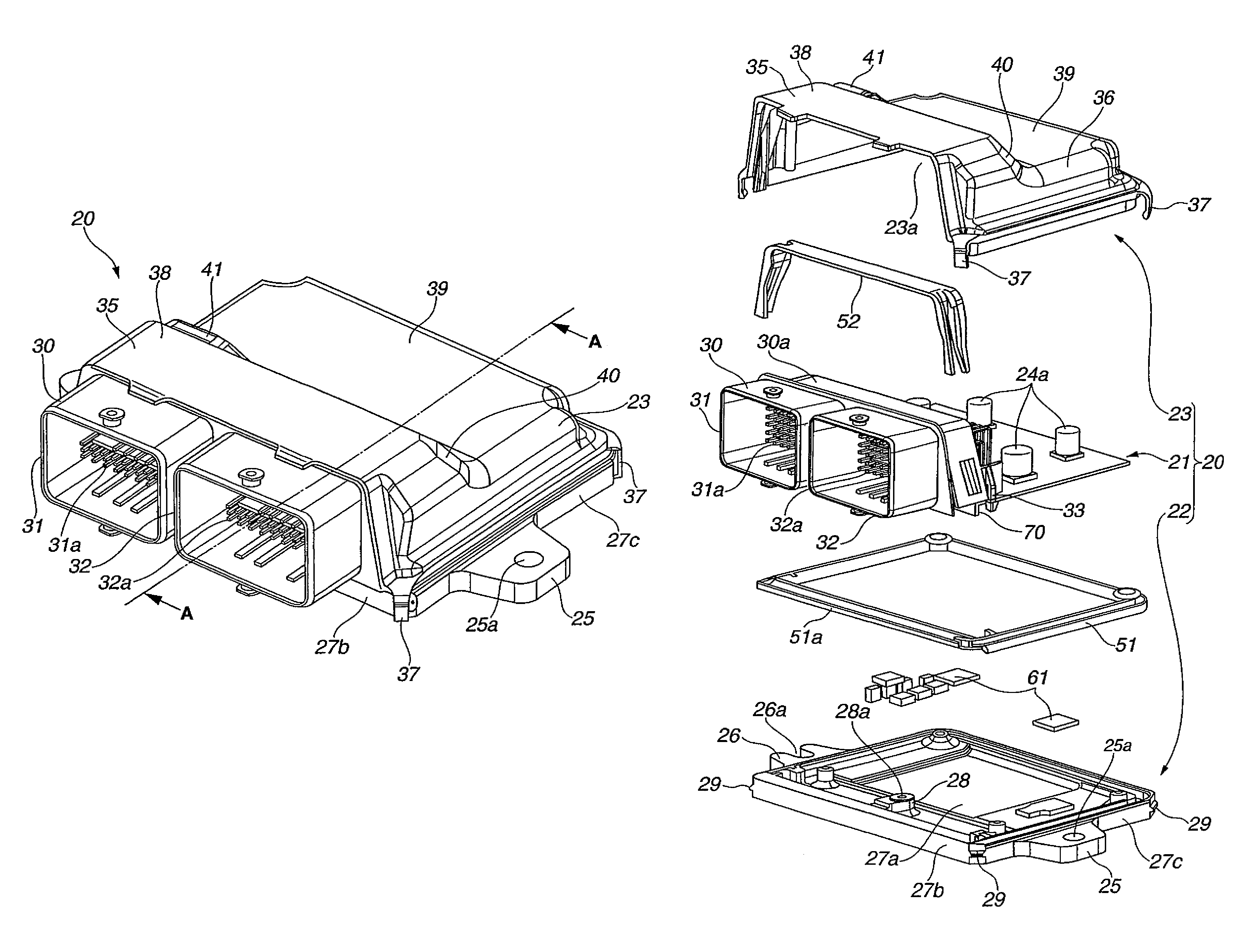
[0044]Referring to FIG. 1 to FIG. 6C, a basic construction of the electronic control device of the first embodiment is explained. In the basic construction of the first embodiment, electronic control device 20 includes a pair of housing members (case 22 and cover 23 as explained later) which cooperate to form a housing, and circuit board 21 accommodated in an inside space within the housing. In the following explanation, the expression “vertical direction” of electronic control device 20 as shown in FIG. 1 to FIG. 3, that is, a thickness direction of circuit board 21 may be used as a vertical direction of electronic control device 20 itself. However, the vertical direction of electronic control device 20 itself does not always correspond to a vertical direction of the vehicle. In a case where electronic control device 20 is mounted to the vehicle in an upright attitude, the vertical direction of electronic control device 20 as shown in FIG. 1 extends along a forwar...


PUM


Abstract

An electronic control device including a circuit board, a connector with connector pins having a board connecting portion at which the connector pins are electrically connected with the circuit board, a pair of housing members accommodating the circuit board and the connector therebetween, a waterproof seal portion through which connection between the connector and the pair of housing members and connection between the pair of housing members are provided in a fluid-tight manner, the waterproof seal portion including a connector-side waterproof seal portion disposed between the connector and one of the pair of housing members which is opposed to the board connecting portion of the connector pins, and a barrier portion disposed between the board connecting portion of the connector pins and the connector-side waterproof seal portion.

Description

BACKGROUND OF THE INVENTION[0001]The present invention relates to an electronic control device for a vehicle which includes a circuit board accommodated in a protection space within a housing.[0002]A generally known electronic control device such as an engine control unit, a control unit for an automatic transmission, etc. which is installed in a vehicle, includes a housing formed by a pair of housing members joined with each other, and a circuit board accommodated in a protection space (for instance, a waterproof space) within the housing. The circuit board is equipped with electronic parts mounted thereto and a connector attached thereto.[0003]A so-called connector horizontal exit electronic control device in which a portion of a connector attached to the circuit board is exposed outside through a window provided on a side face of the housing includes a waterproof seal portion formed on a connecting portion between the connector and the pair of housing members. The waterproof seal...

Claims


Application Information

Patent Timeline
Patent Type & Authority Patents(United States)
IPC IPC(8): H05K1/00H01R13/52H05K7/14H05K5/00
CPCH01R13/5202H05K5/0069H05K7/14
Inventor YAMANAKA, KENTAROOHHASHI, HIRONORIKAWAI, YOSHIO
Owner HITACHI ASTEMO LTD
Learn More