
Label printing scale device

a technology of printing scale and label, which is applied in the direction of measuring device, weighing apparatus details, instruments, etc., to achieve the effect of occupying as much space, reducing manufacturing costs, and compact device width

Inactive Publication Date: 2015-07-28
ISHIDA CO LTD
View PDF28 Cites 15 Cited by
  • Summary
  • Abstract
  • Description
  • Claims
  • Application Information

AI Technical Summary

Benefits of technology

The invention provides a temperature-compensated label printing scale device that can be made at a low cost and limited manufacturing costs. The device is compact and can be placed on show cases without taking up too much space. The thin upper casing on which the weighing tray is mounted can be used separately from the thicker lower casing housing the power-generation circuit. Even when a fan is installed for cooling the power-generation circuit, there is no effect on the load cell as the fan does not produce air flow.

Problems solved by technology

However, as disclosed in Japanese Laid-Open Patent Application No. 2002-310776, Japanese Patent Registration No. 4449310, and Japanese Laid-Open Patent Application No. 2009-14455, in such measuring devices, the load cell, which does not readily tolerate changes in temperature, is housed together in the main casing with power-generation circuits, printers, and other components that generate heat due to electrical currents, and therefore particular care must be taken with temperature compensation for load cells housed in such devices.

Method used


Image

  • Label printing scale device
  • Label printing scale device
  • Label printing scale device

Examples


Embodiment Construction

[0035]An embodiment of the invention will be described below on the basis of the drawings.

[0036]FIG. 1 shows an exterior perspective view of a label printing scale device A according to an embodiment of the invention. In particular, this diagram shows a state in which an upper casing 100 has been taken off a lower casing 200, where a weighing tray B is loaded on the upper casing 100.

[0037]In FIG. 1, the label printing scale device A is provided with the lower casing 200 and the upper casing 100. A touch panel 300 is attached to the front surface of the lower casing 200, and a customer-side display part 310 is attached to the back surface of the lower casing 200. The weighing tray B is mounted on the upper casing. The casings 100, 200 are separable, and the upper casing 100 can be laid on top of the lower casing 200.

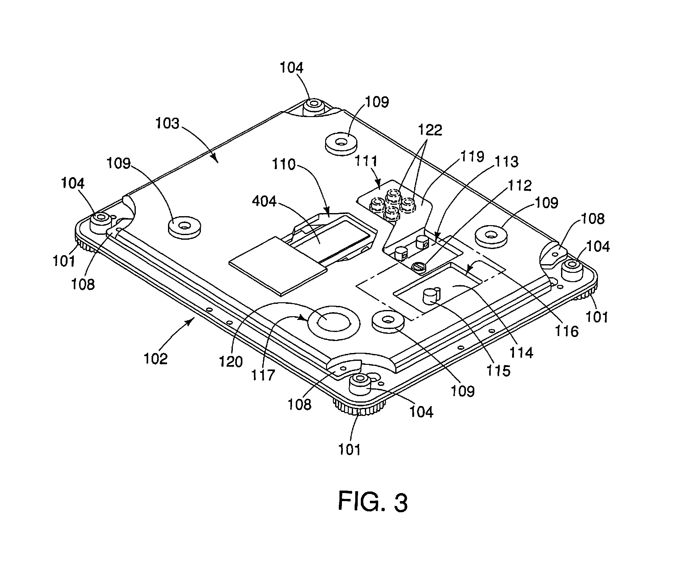
[0038]As shown in the cross-sectional diagram of FIG. 2, the upper casing 100 includes a metal base member 102, to which leg parts 101 are provided, and a metal tray-rece...


PUM


Abstract

A label printing scale device includes separable casings that are vertically overlaid in two levels, one on top of the other. Specifically, the label printing scale device includes an upper casing housing at least a load cell and a circuit part, and a lower casing housing at least power-generation circuit, a printer, and a control part.

Description

TECHNICAL FIELD[0001]The invention relates to a label printing scale device used for selling meat, prepared foods, or the like by weight.BACKGROUND ART[0002]It is well-known that the output sensitivity and / or zero-point output of load cells used as weight sensors are often influenced by changes in the temperature of their surroundings. Examples of attempts to solve this problem in measuring devices in which these load cells are built-in include connecting temperature-compensating resistance to the output circuit of the load cell (Japanese Patent Registration No. 3534205), implementing automatic tracking for automatically updating the zero point during periods of no load (Japanese Patent Registration No. 3568609), and detecting the temperature within the casing, applying a correction coefficient to the output of the load cell, and reducing the effects due to temperature drift (Japanese Laid-Open Patent Application No. 2008-64497).[0003]On the other hand, at super markets and other co...

Claims


Application Information

Patent Timeline
Patent Type & Authority Patents(United States)
IPC IPC(8): G01G19/40G01G23/38G01G19/414G01G21/28G01G23/48G01G23/37
CPCG01G21/28G01G19/4144G01G23/38G01G23/48G01G23/3728
Inventor KAWAMURA, RYOICHIAOYAMA, KENGO
Owner ISHIDA CO LTD
Learn More