Eureka AIR delivers breakthrough ideas for toughest innovation challenges, trusted by R&D personnel around the world.

Power connector assembly

a technology of power connectors and assembly parts, which is applied in the direction of coupling contact parts, coupling device connections, electrical apparatus, etc., can solve the problems of increasing the fabrication cost of the size of the first electrical connector, and the difficulty in minimizing the conventional power connector assembly, etc., to achieve cost-effectiveness, reduce volume, and increase the effect of the power connector assembly

Inactive Publication Date: 2015-07-21
DELTA ELECTRONICS INC
View PDF5 Cites 1 Cited by
  • Summary
  • Abstract
  • Description
  • Claims
  • Application Information

AI Technical Summary

Benefits of technology

[0006]The present invention provides a power connector assembly. The power connector assembly comprises a first electrical connector with plural first conducting terminals and a second electrical connector with plural second conducting terminals. The first conducting terminal has a flat contacting part. The second conducting terminal has a terminal-clamping part. The flat contacting part is clamped by the terminal-clamping part, so that electrical connection between the first electrical connector and the second electrical connector is established. Moreover, at least two first wires are connected with each other in parallel, so that the at least two first conducting terminals that are electrically connected with the parallel-connected first wires are connected with each other in parallel. Consequently, when compared with the conventional power connector assembly, the power connector assembly of the present invention has reduced volume. Moreover, the first conducting terminals and the second conducting terminals may be made of the cost-effective material that is capable of withstanding the lower current while complying with safety regulations. Since the power connector assembly of the present invention can be applied to the power supply system or the electrical device that requires higher electrical power, the applications of the power connector assembly are more extensive.

Problems solved by technology

However, since the conducting terminals of the first electrical connector of the conventional power connector assembly are cylindrical, the volume of the first electrical connector is larger, and it is difficult to minimize the conventional power connector assembly.
Since this material is costly, the fabricating cost of the conventional power connector assembly is increased.
Moreover, since each of the first electrical connector and the second electrical connector of the conventional power connector assembly has at most three conducting terminals, the conventional power connector assembly can only be applied to specified kinds of power supply systems and specified kinds of electrical devices.
In other words, the applications of the conventional power connector assembly are restricted.

Method used


Image

  • Power connector assembly
  • Power connector assembly
  • Power connector assembly

Examples


Embodiment Construction

[0017]The present invention will now be described more specifically with reference to the following embodiments. It is to be noted that the following descriptions of preferred embodiments of this invention are presented herein for purpose of illustration and description only. It is not intended to be exhaustive or to be limited to the precise form disclosed.

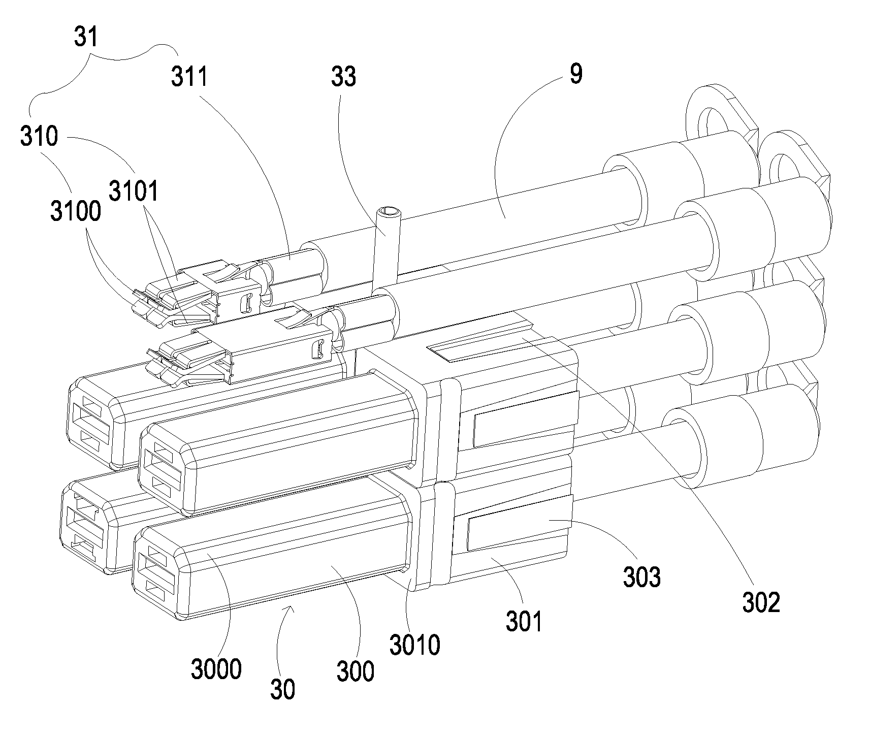
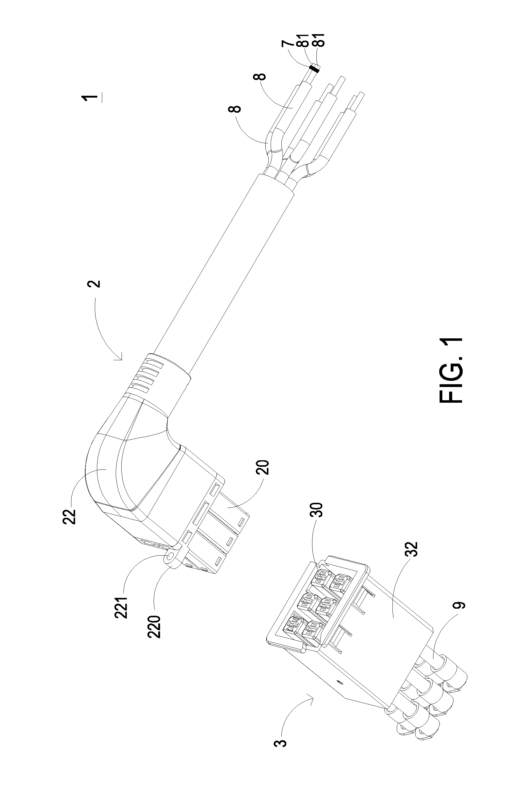
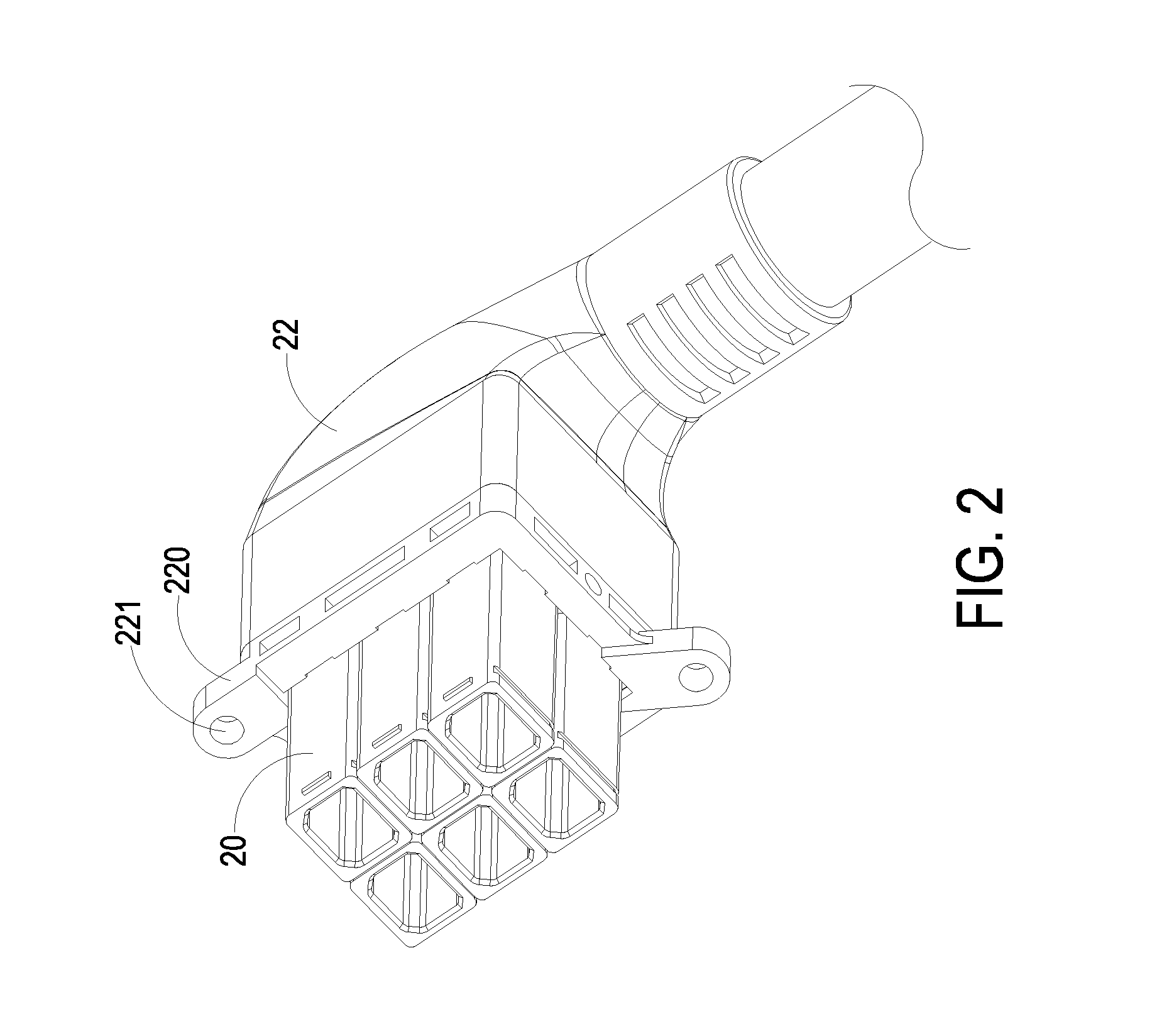
[0018]FIG. 1 is a schematic exploded view illustrating a power connector assembly according to an embodiment of the present invention. As shown in FIG. 1, the power connector assembly 1 comprises a first electrical connector 2 and a second electrical connector 3, which mate with each other. The first electrical connector 2 may be electrically connected with an electrical device (not shown) such as an industrial computer or a cloud data center. The second electrical connector 3 may be electrically connected with a power supply system (not shown) such as a battery, a power supply or an uninterruptible power supply. After the first ...


PUM


Abstract

A power connector assembly includes a first electrical connector and a second electrical connector mating with the first electrical connector. The first electrical connector includes a plurality of first hollow tubes. Moreover, a plurality of first conducting terminals are disposed within the first hollow tubes, selectively. Each first conducting terminal has a flat contacting part. The second electrical connector includes a plurality of second hollow tubes corresponding to the first hollow tubes. Moreover, a plurality of second conducting terminals are disposed within the second hollow tubes, selectively. Each second conducting terminal has a terminal-clamping part. When the first electrical connector and the second electrical connector are combined together, the flat contacting part of each first conducting terminal is clamped by the terminal-clamping part of the corresponding second conducting terminal, so that electrical connection between the first electrical connector and the second electrical connector is established.

Description

FIELD OF THE INVENTION[0001]The present invention relates to a power connector assembly, and more particularly to a power connector assembly having a reduced volume and having extensive applications.BACKGROUND OF THE INVENTION[0002]Recently, a power connector assembly has been widely used in a power network, a power transmission system, a power distribution system, a power supply system or an electrical device to be used as an interface of power transmission and connection. For example, a power supply system (e.g. a battery, a power supply or an uninterruptible power supply) and an electrical device (e.g. an industrial computer or a cloud data center) may be in communication with each other through two electrical connectors in order to achieve electrical connection and power transmission.[0003]Conventionally, the power connector assembly comprises a first electrical connector and a second electrical connector. The first electrical connector may be connected with an electrical device...

Claims


Application Information

Patent Timeline
Patent Type & Authority Patents(United States)
IPC IPC(8): H01R4/50H01R13/514H01R13/04H01R13/11
CPCH01R13/514H01R13/04H01R13/113
Inventor HUANG, SHIN-IYANG, YUNG-HUNG
Owner DELTA ELECTRONICS INC
Why Eureka
Eureka Blog
Learn More