Electromagnetic fuel injection valve

a fuel injection valve and electromagnetic technology, applied in the direction of fuel injection apparatus, machine/engine, feed system, etc., can solve the problems of sliding member and fixed core unbalanced load (side thrust), sliding portion wear more quickly, sliding member wear more quickly, opening and closing response of the valve element is reduced, etc., to achieve high frictional resistance, reduce the opening and closing response of the valve element, the effect of high frictional resistan

Active Publication Date: 2015-07-14
HITACHI ASTEMO LTD
View PDF8 Cites 3 Cited by
  • Summary
  • Abstract
  • Description
  • Claims
  • Application Information

AI Technical Summary

Benefits of technology

[0005]Heretofore, in order to stabilize an opening and closing attitude of a valve element in such an electromagnetic fuel injection valve, it is known that a rear end portion of a valve stem of the valve element is extended into a hollow portion of a fixed core, and a sliding member is secured to the rear end portion and slidably supported on an inner peripheral surface of the fixed core. Meanwhile, an unbalanced load (side thrust) is applied between the sliding member and the fixed core in some cases due to manufacturing errors of each part, an attraction force in an oblique direction generated between the fixed core and a movable core, or the like. Such an application causes a high frictional resistance between the sliding member and the fixed core, bringing about inconveniences that the opening and closing response of the valve element is reduced, and that the sliding portion is worn more quickly.
[0006]The present invention has been made in view of such a circumstance. An object of the present invention is to provide the electromagnetic fuel injection valve, which is configured to absorb an unbalanced load applied to sliding portions between a fixed core and a valve stem due to manufacturing errors or the like, thereby enabling a reduction in the frictional resistance of the sliding portions.
[0008]According to the first aspect of the present invention, the annular gap is provided at least at one of the location between the fixed core and the guide bush and the location between the valve stem and the sliding member, within the sliding regions of the guide bush and the sliding member. Hence, when an unbalanced load is applied between the guide bush and the sliding member due to manufacturing errors, an attraction force in an oblique direction generated between the fixed and the movable cores, or the like, a portion of the guide bush or the sliding member corresponding to the annular gap is elastically deformed so that the unbalanced load can be absorbed. This ensures that the guide bush and the sliding member smoothly slide on each other, making it possible to enhance the opening and closing response of the valve element.
[0010]According to the second aspect of the present invention, the annular gap is provided at each of the location between the fixed core and the guide bush and the location between the valve stem and the sliding member, within the sliding regions of the guide bush and the sliding member. Hence, when the unbalanced load is applied between the guide bush and the sliding member, portions of both the guide bush and the sliding member corresponding to the annular gaps, respectively, are elastically deformed so that the unbalanced load can be effectively absorbed. This ensures that the guide bush and the sliding member more smoothly slide on each other, making it possible to further enhance the opening and closing response of the valve element.
[0011]Furthermore, in assembling the fuel injection valve, when the guide bush is press fitted in the inner peripheral surface of the fixed core, the portion of the guide bush corresponding to the annular gap at an outer periphery of the guide bush is a non-press fitting portion. Hence, a sliding surface of the guide bush can be prevented from being deformed by a press fitting load of the guide bush to the fixed core. Meanwhile, when the sliding member is press fitted on an outer peripheral surface of the valve stem, the portion of the sliding member corresponding to the annular gap at an inner periphery of the sliding member is a non-press fitting portion. Hence, a sliding portion of the sliding member can be prevented from being deformed by a press fitting load of the sliding member to the valve stem.
[0013]According to the third aspect of the present invention, the outer peripheral surface of the sliding member is provided with the cutout configured to make the hollow portion of the fixed core communicate with the inside of the valve housing. This enables fuel to flow from the hollow portion of the fixed core toward the valve housing through the cutout without being interfered with the sliding member.

Problems solved by technology

Meanwhile, an unbalanced load (side thrust) is applied between the sliding member and the fixed core in some cases due to manufacturing errors of each part, an attraction force in an oblique direction generated between the fixed core and a movable core, or the like.
Such an application causes a high frictional resistance between the sliding member and the fixed core, bringing about inconveniences that the opening and closing response of the valve element is reduced, and that the sliding portion is worn more quickly.
Hence, when an unbalanced load is applied between the guide bush and the sliding member due to manufacturing errors, an attraction force in an oblique direction generated between the fixed and the movable cores, or the like, a portion of the guide bush or the sliding member corresponding to the annular gap is elastically deformed so that the unbalanced load can be absorbed.

Method used


Image

  • Electromagnetic fuel injection valve
  • Electromagnetic fuel injection valve
  • Electromagnetic fuel injection valve

Examples


Embodiment Construction

[0018]An embodiment of the present invention will be described below based on the accompanying drawings.

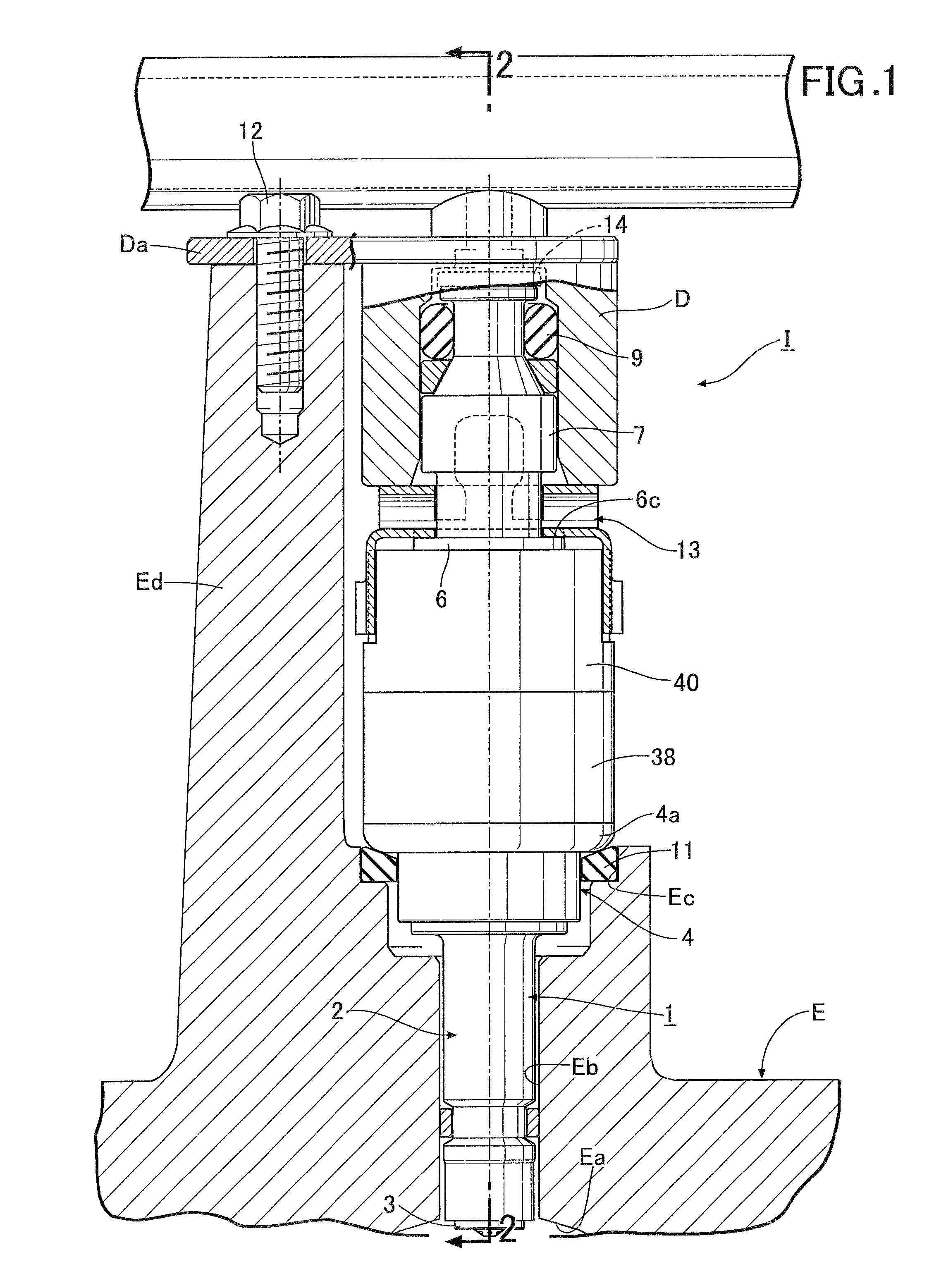
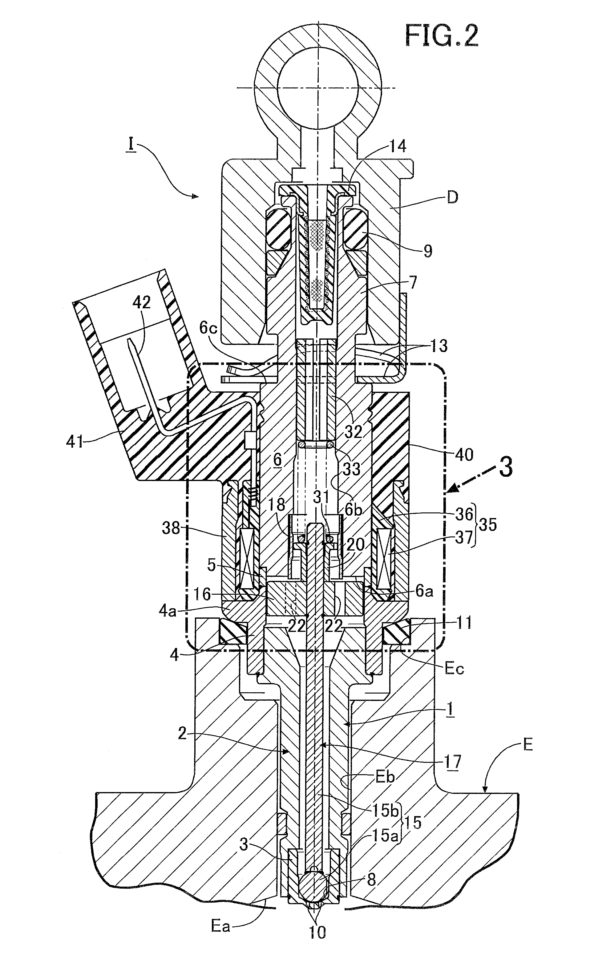
[0019]In FIGS. 1 and 2, a cylinder head E of an engine is provided with a fitting hole Eb open to a combustion chamber Ea. An electromagnetic fuel injection valve I is fitted in the fitting hole Eb. The fuel injection valve I is capable of injecting fuel toward the combustion chamber Ea. Here, in the fuel injection valve I, a fuel injection side is referred to as a front side, and a fuel inlet side is referred to as a rear side.

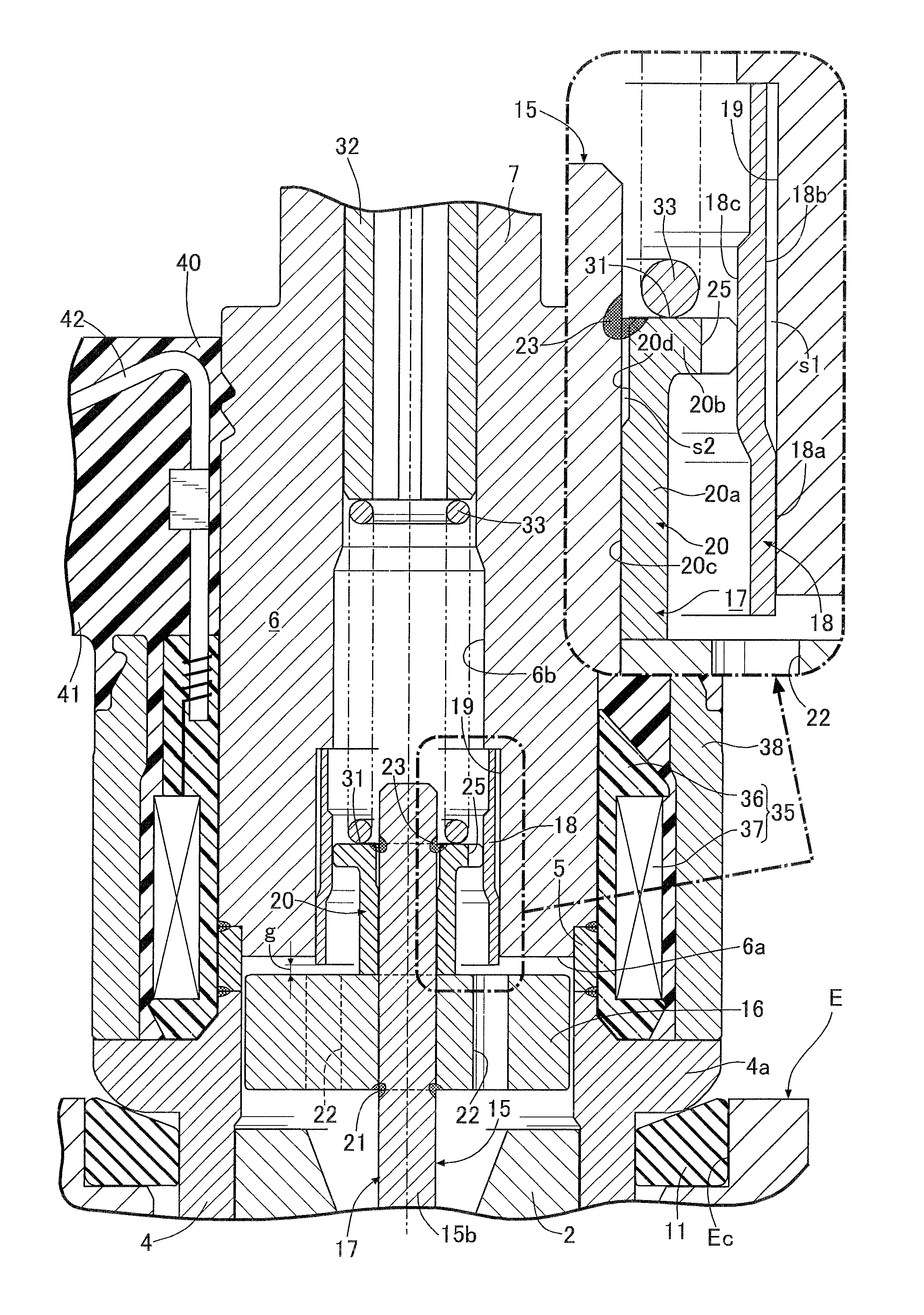
[0020]A valve housing 1 of the fuel injection valve I includes: a hollow cylindrical valve housing body 2; a bottomed cylindrical valve seat member 3 fitted in and welded to an inner peripheral surface at a front end portion of the valve housing body 2; a magnetic cylindrical body 4 fitted in and welded to an outer periphery of a large diameter portion 2a at a rear end of the valve housing body 2; and a non-magnetic cylindrical body 5 coaxially connected to...


PUM


Abstract

In an electromagnetic fuel injection valve which is configured to absorb an unbalanced load applied to sliding portions between a fixed core and a valve stem, thereby enabling a reduction in a frictional resistance of the sliding portions, a guide bush is press fitted in an inner peripheral surface of the fixed core, the valve element includes a valve part configured to cooperate with the valve seat, and the valve stem continuously provided to the valve part and extending toward the guide bush, a sliding member configured to be slidably fitted to an inner peripheral surface of the guide bush is press fitted on the valve stem, wherein an annular gap is provided at least at one of a location between the fixed core and the guide bush and a location between the valve stem and the sliding member, within sliding regions of the guide bush and the sliding member.

Description

BACKGROUND OF THE INVENTION[0001]1. Field of the Invention[0002]The present invention relates to an improvement of an electromagnetic fuel injection valve comprising: a valve housing having a valve seat at a front end thereof; a hollow fixed core continuously provided to a rear end of the valve housing; a movable core disposed opposite to an attraction surface of the fixed core; a coil disposed on an outer periphery of the fixed core; a valve element connected to the movable core to cooperate with the valve seat; and a valve spring configured to bias the valve element in a valve closing direction, wherein the movable core is caused to be attracted to the fixed core by energizing the coil so as to open the valve element.[0003]2. Description of the Related Art[0004]Such an electromagnetic fuel injection valve is known as disclosed in Japanese Patent Application Laid-open No. 2010-180785.SUMMARY OF THE INVENTION[0005]Heretofore, in order to stabilize an opening and closing attitude of ...

Claims


Application Information

Patent Timeline
Patent Type & Authority Patents(United States)
IPC IPC(8): F02M51/06F02M61/12F02M61/10F02M61/14
CPCF02M61/12F02M51/0625F02M51/0675F02M61/10F02M61/14F02M2200/856
Inventor SUZAKA, JUNYAMACHIDA, KEISUKEKONDO, DAISUKETAKENAKA, RYOSUKE
Owner HITACHI ASTEMO LTD
Why Eureka
Try Eureka