Locking device for adjusting element
a technology of locking device and adjusting element, which is applied in the direction of horology, instruments, gearing, etc., can solve the problems of difficult precise locking, and achieve the effect of convenient and inexpensive installation and attachmen
- Summary
- Abstract
- Description
- Claims
- Application Information
AI Technical Summary
Benefits of technology
Problems solved by technology
Method used
Image
Examples
first embodiment
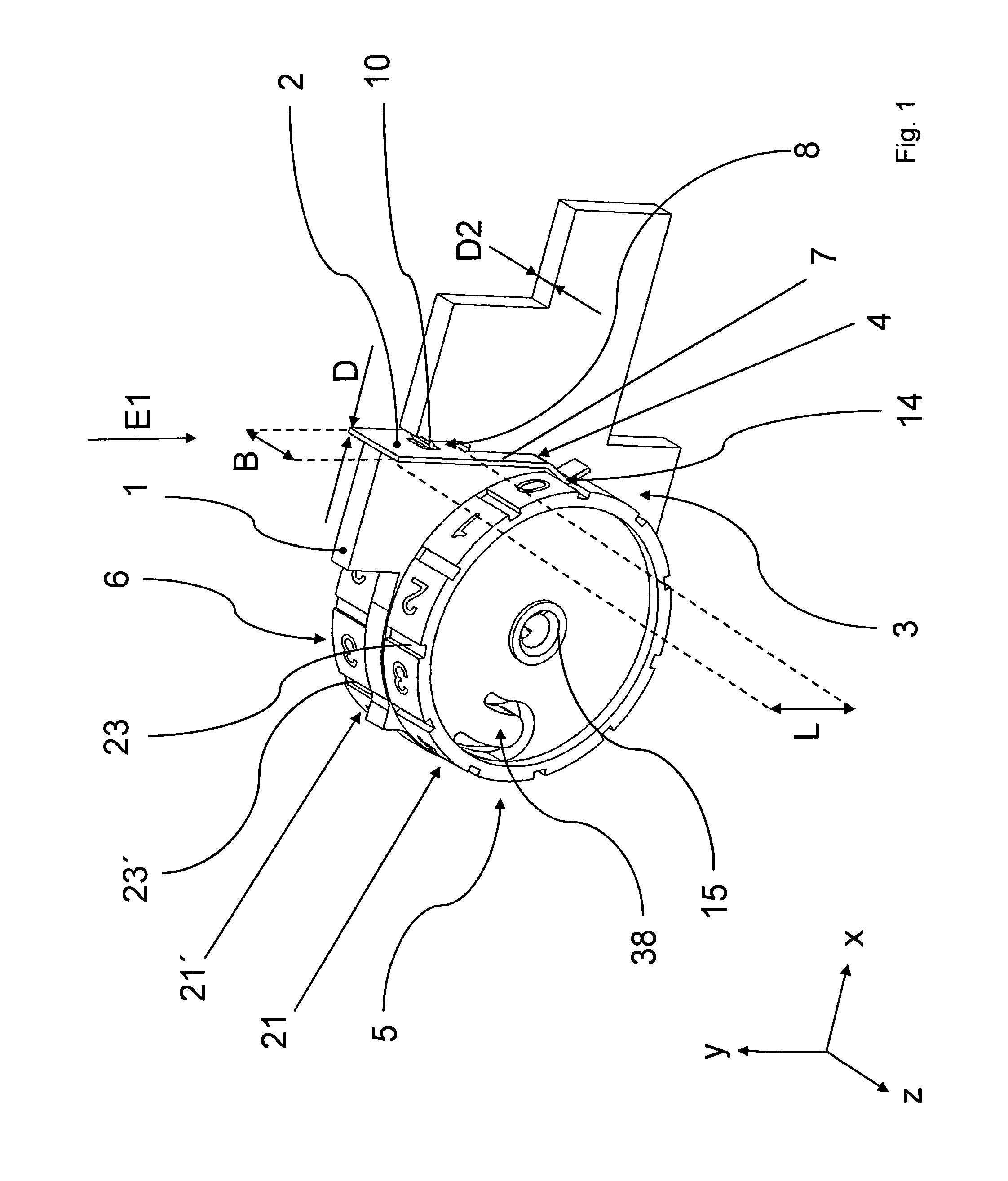
[0055]FIG. 1 shows the locking device according to the invention for locking two adjusting means (5, 6) of an addressing device which are situated on a printed circuit board (1).
[0056]Each of the two opposite sides of the printed circuit board (1) extending in the x-y plane has a circuit arrangement (3) having an adjustable electrical component (not shown) which may be adjusted by adjusting means (5, 6) to allow addressing to be set. The adjusting means (5, 6) are rotatable and designed as thumbwheels by way of example. A rotatable adjusting means advantageously has a bearing in the center via which the adjusting means may be rotatably supported on the printed circuit board, and which may also be attached to the printed circuit board by means of a rivet, for example, which during installation is to be pushed through the bearing and through a hole in the printed circuit board.
[0057]Markings (21, 21′), preferably in number format, are affixed in each case to the peripheral surfaces of...
second embodiment
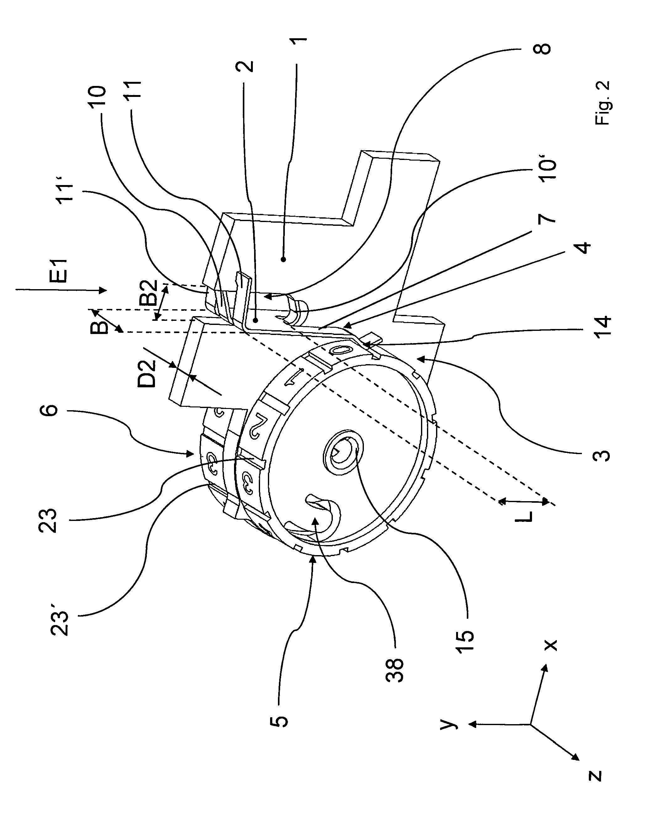
[0065]FIG. 2 shows the device according to the invention for locking adjusting means (5, 6) situated on a printed circuit board (1); in contrast to the device shown in FIG. 1, this embodiment has a wider oblong recess (8) having a width (B2) in the printed circuit board (1). In addition, the base plate (2) has two spring clamping tabs (10, 10′) on its two broad sides which are inclined transversely with respect to the insertion direction (E1), and which thus allow improved pretensioning of the base plate (2) of the device according to the invention in the oblong recess (8).
[0066]In another departure from FIG. 1, the base plate (2) of the device according to FIG. 2 has a material projection (11, 11′) on each side of the printed circuit board (1) on its broad side, the material projection likewise being inclined transversely with respect to the insertion direction (E1) and fixing the base plate (2) in the oblong recess (8) in the z direction.
third embodiment
[0067]FIG. 3 and FIG. 4 show a perspective view, in each case from a different viewing direction, of the device according to the invention for locking adjusting means (5, 6), which are mounted on opposite sides of a printed circuit board (1) and in each case fixed, mounted, or attached to same by means of a rivet (16).
[0068]FIG. 5 shows the embodiment of the device for locking according to FIG. 3 in a side view, a front view, and a top view.
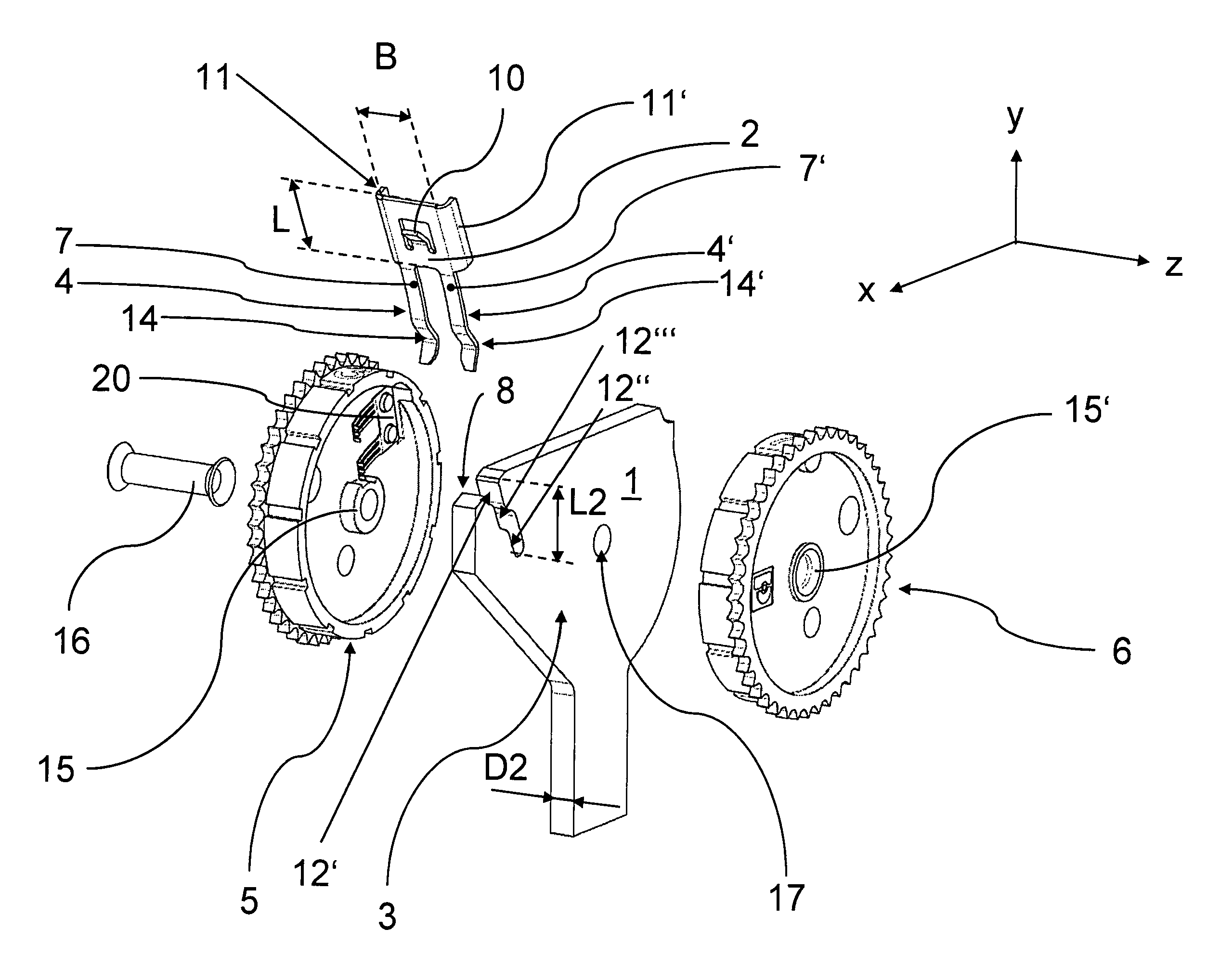
[0069]FIG. 6 shows an exploded view of the components of the device according to the invention corresponding to FIG. 3 and FIG. 4, in a perspective view. FIG. 6 also shows an electrical consumer (20), which in each case is situated on the inside of the thumbwheels (5, 6) which function as adjusting means, and is used for transmitting an electrical current between resistance tracks situated in each case on the circuit arrangements (3) on both sides of the printed circuit board (1).
[0070]FIG. 7 shows this third embodiment in a side view without an ...
PUM
 Abstract
Description
Claims
Application Information
 - R&D
- Intellectual Property
- Life Sciences
- Materials
- Tech Scout
- Unparalleled Data Quality
- Higher Quality Content
- 60% Fewer Hallucinations
Browse by: Latest US Patents, China's latest patents, Technical Efficacy Thesaurus, Application Domain, Technology Topic, Popular Technical Reports.
© 2025 PatSnap. All rights reserved.Legal|Privacy policy|Modern Slavery Act Transparency Statement|Sitemap|About US| Contact US: help@patsnap.com


