Control device to control deterioration of batteries in a battery stack

a control device and battery technology, applied in secondary cells servicing/maintenance, instruments, electrochemical generators, etc., can solve the problems of short lifetime of stationary battery systems, insufficient resolution of variations in deterioration between batteries, etc., to achieve the effect of suppressing variations in deterioration rates and improving the lifetime of storage battery systems

Active Publication Date: 2015-07-07
NISSAN MOTOR CO LTD
View PDF14 Cites 1 Cited by
  • Summary
  • Abstract
  • Description
  • Claims
  • Application Information

AI Technical Summary

Benefits of technology

[0005]The problem to be solved by the present invention resides in that, in a battery control device for controlling a battery system composed of a plurality of batteries connected in parallel, without using a temperature control system, the variations in deterioration between batteries connected in parallel may be suppressed thereby improving the lifetime of the storage battery system.
[0007]According to the present invention, since the amount of power to be input to or output from each battery is controlled to cause the deterioration rates for respective storage batteries calculated based on the temperature and energy amount of each battery connected in parallel to be close to each other, the variations in deterioration rates may be suppressed and, as a result, the lifetime of the storage battery system may be improved.

Problems solved by technology

When placed in such a different temperature environment, the deterioration rate may differ from battery to battery so that the variation in deterioration between the batteries are facilitated with the result that the overall lifetime of the stationary battery system becomes short.
However, in the prior art described above, while the temperature difference is occurring between batteries, only the timing of battery charging is controlled, and since no consideration is given to the deterioration rate attributable to energy amount of storage battery, there is a problem that variations in deterioration between batteries may not be sufficiently resolved.

Method used


Image

  • Control device to control deterioration of batteries in a battery stack
  • Control device to control deterioration of batteries in a battery stack
  • Control device to control deterioration of batteries in a battery stack

Examples


Embodiment Construction

[0016]An embodiment according to the present invention will now be described below with reference to the accompanying drawings.

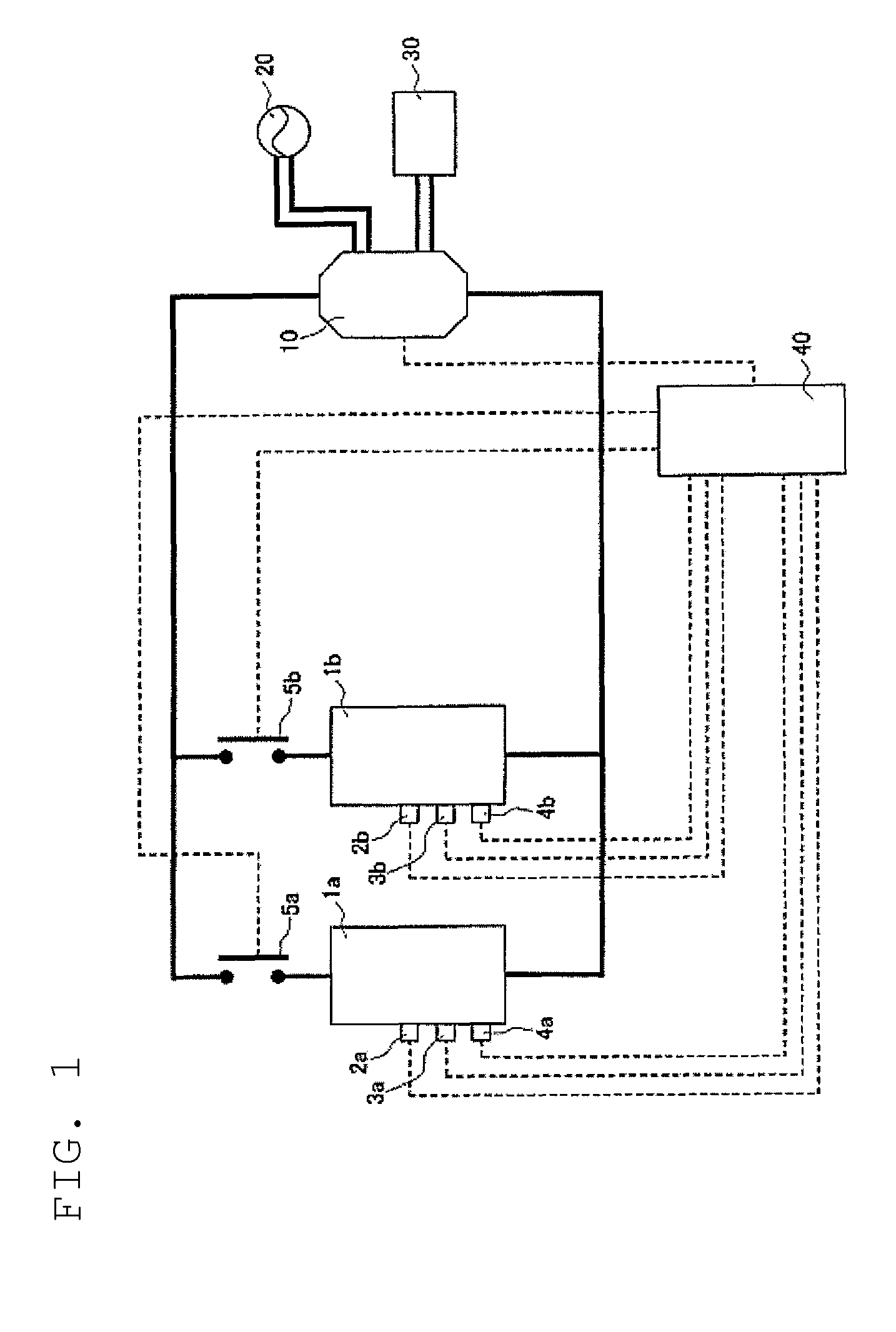
[0017]FIG. 1 is a block diagram showing a storage battery system according to the present embodiment. Although the battery system in the present embodiment is explained as applied to an example of stationary storage battery system, no particular limitation is present to this example.

[0018]As shown in FIG. 1, the storage battery system in the present embodiment is provided with a first storage battery 1a, second storage battery 1b, a converter 10, an AC power source 20, an AC load 30, and a controller 40. The first storage battery 1a and the second storage battery 1b are connected to each other in parallel through the power line, and are further connected to a converter 10. Further, the first storage battery 1a and the second storage battery 1b can receive via the converter 10 power from AC power source 20. Note that, in FIG. 1, the bold solid line indicates ...


PUM

PropertyMeasurementUnit
temperatureaaaaaaaaaa
energyaaaaaaaaaa
poweraaaaaaaaaa

Abstract

Provided is a storage battery system comprising a plurality of storage batteries connected in parallel, characterized by detecting the temperature and energy amount of each battery connected in parallel, calculating the deterioration rate of each battery based on the detected temperature and energy-amount, and controlling the power amount to be inputted to and output from each battery so that the deterioration rate of each storage battery will come closer to each other.

Description

TECHNICAL FIELD[0001]The present invention relates to a battery control device for controlling a storage battery system consisting of a plurality of storage batteries connected in parallel.BACKGROUND[0002]Conventionally, as a storage battery system used in relatively severe temperature environments, a stationary storage battery system is known. The stationary storage battery system is normally used by connecting a plurality of batteries in parallel. However, in a structure in which a plurality of batteries is connected in parallel, each battery connected in parallel is often placed in a different temperature environment. When placed in such a different temperature environment, the deterioration rate may differ from battery to battery so that the variation in deterioration between the batteries are facilitated with the result that the overall lifetime of the stationary battery system becomes short. On the other hand, in order to place each battery in the same temperature environment,...

Claims


Application Information

Patent Timeline
Patent Type & Authority Patents(United States)
IPC IPC(8): H02J7/00H01M10/44H01M10/48H01M10/42H02J7/04G01R31/36H02J7/02
CPCH02J7/00H01M10/44H01M10/441H01M10/443H01M10/48H01M10/482H01M10/486H02J7/0013H02J7/047H01M10/425H02J7/0077H02J7/045Y02T10/7044H02J7/042H02J7/04H02J7/0088Y02T10/7038H02J7/0091H02J7/0086H01M2010/4271G01R31/3679G01R31/392H02J7/007194Y02E60/10H02J7/007182Y02T10/70
Inventor FUJITA, TAKESHIKINOSHITA, TAKUYAYANAGIHARA, YASUHIRO
Owner NISSAN MOTOR CO LTD
Why Eureka
Try Eureka