
Wound dressing and method of use

a wound dressing and negative pressure technology, applied in the field of wound dressings and wound treatments, can solve the problems of inconvenient storage of exuding material in wound dressings, inconvenient use, and costly and bulky provision of canisters,

Active Publication Date: 2015-06-23
SMITH & NEPHEW PLC
View PDF674 Cites 244 Cited by
  • Summary
  • Abstract
  • Description
  • Claims
  • Application Information

AI Technical Summary

Benefits of technology

The dressing extends the time between changes, maintains an open flow path, and reduces damage from compressive and shear forces, ensuring continuous TNP therapy by absorbing and managing exudate and forces effectively.

Problems solved by technology

A problem associated with many known techniques is that a separate canister must be provided for storage of such exudate.
Provision of such canisters is costly and bulky and prone to failure.
However, it is known that many different wound types can exude high flow rates of exudate and therefore storage of exuding material in a wound dressing can be problematical since the wound dressing will only have a limited capacity for fluid uptake before a dressing change is required.
This can limit a time of use between dressing changes and can prove costly if many wound dressings are required to treat a given wound.
Whilst such dressings work well in practice, the continuous evaporation of moisture vapor from the dressing can lead to the problem of crust formation in the dressing.
That is to say, because of the continuous drawing of liquid away from the wound site solid particulate matter is more prone to formation and accumulation in the dressing.
Under certain circumstances the build-up of such solid material can lead to blockages forming in the wound dressing in the flowpath between the wound and the source of negative pressure.
This can potentially cause problems in that therapy may need to be halted to change a dressing if the blockages reach a critical level.
Such accidents might cause short term or long term forces to be applied to a dressing covering a wound.
Such force can cause disturbance of a wound bed which can damage a wound site.
Under such conditions lateral forces can entirely upset or tear apart a healing skin graft region.

Method used


Image

  • Wound dressing and method of use
  • Wound dressing and method of use
  • Wound dressing and method of use

Examples


Embodiment Construction

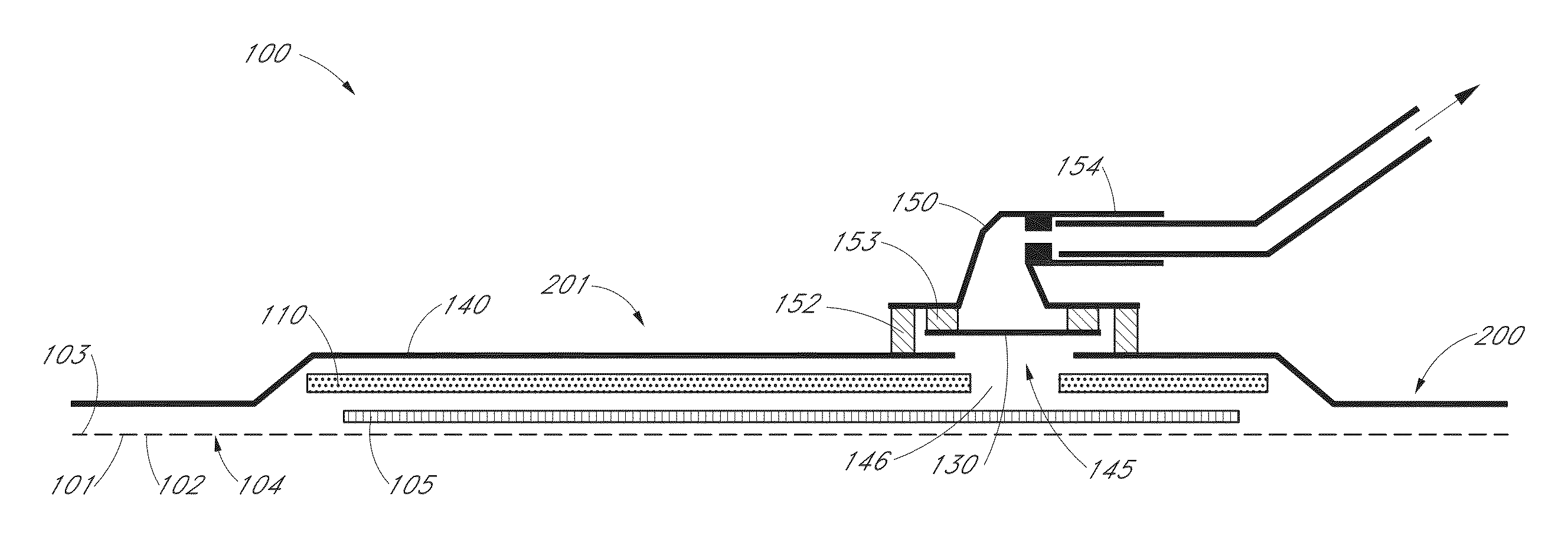
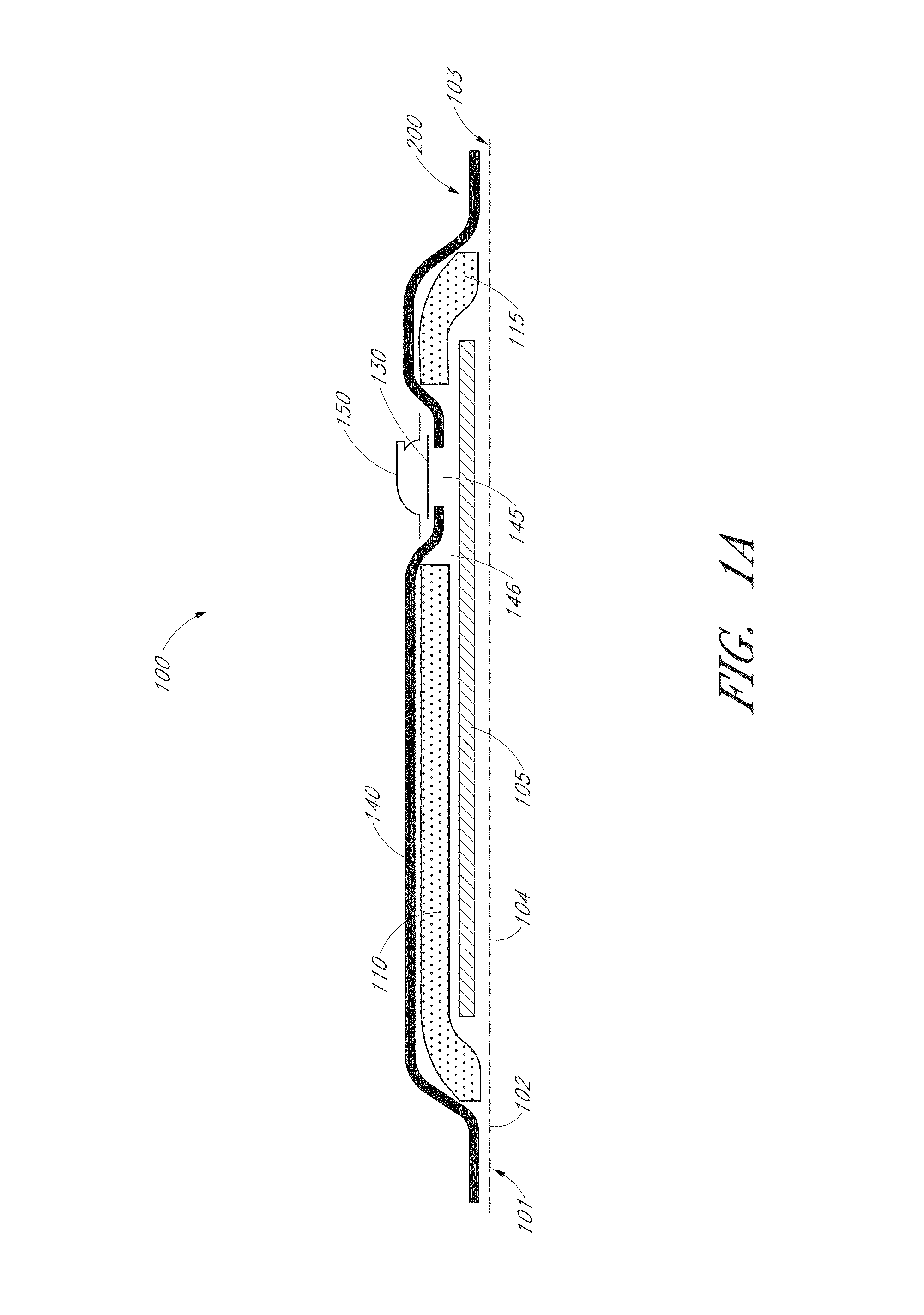
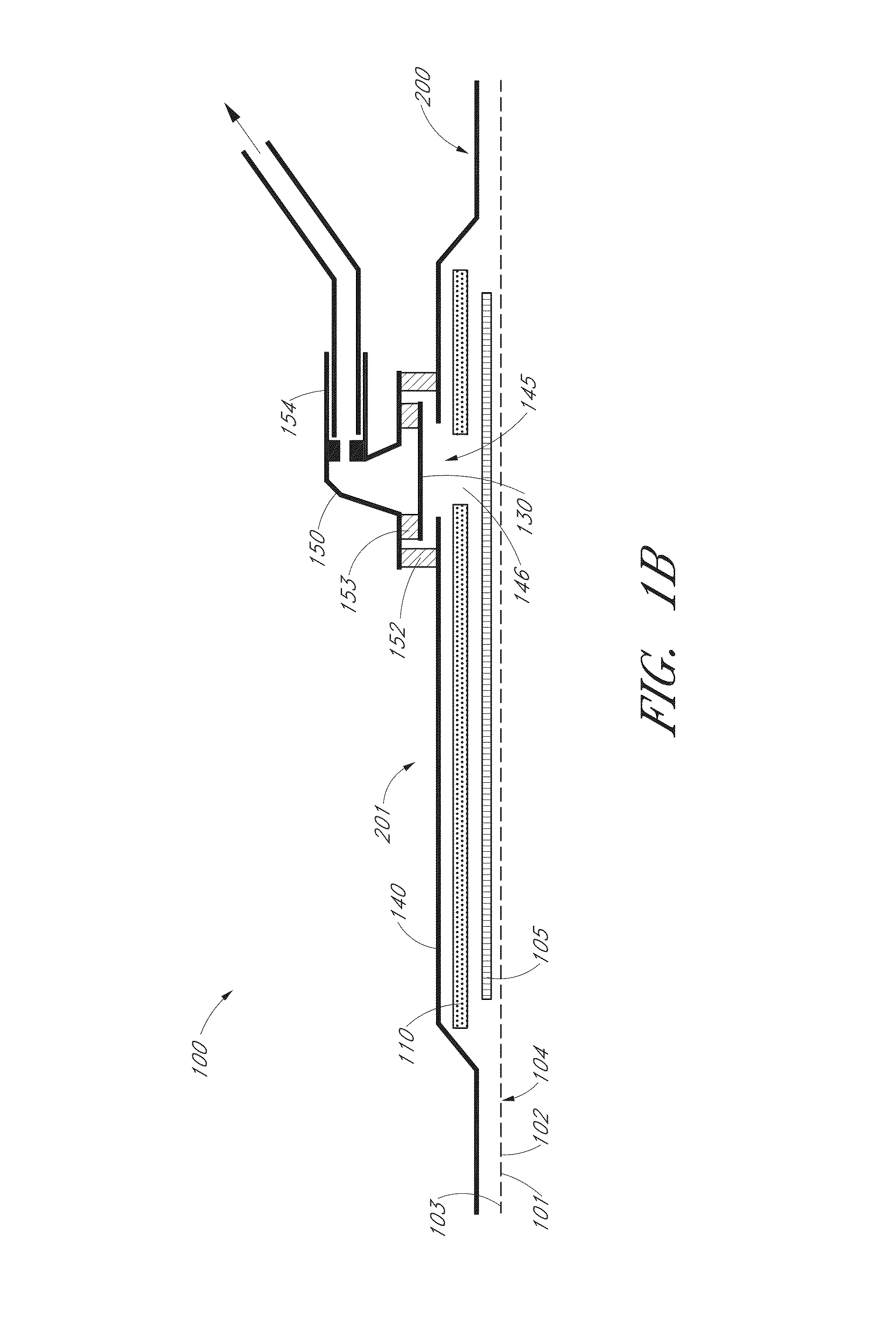
[0132]FIGS. 1A-B illustrate cross sections through a wound dressing 100 according to an embodiment of the invention. A plan view from above the wound dressing 100 is illustrated in FIG. 2 with the line A-A indicating the location of the cross section shown in FIGS. 1A and 1B. It will be understood that FIGS. 1A-B illustrate a generalized schematic view of an apparatus 100. It will be understood that embodiments of the present invention are generally applicable to use in TNP therapy systems. Briefly, negative pressure wound therapy assists in the closure and healing of many forms of “hard to heal” wounds by reducing tissue oedema; encouraging blood flow and granular tissue formation; removing excess exudate and may reduce bacterial load (and thus infection risk). In addition, the therapy allows for less disturbance of a wound leading to more rapid healing. TNP therapy systems may also assist on the healing of surgically closed wounds by removing fluid and by helping to stabilize the ...


PUM

PropertyMeasurementUnit
pressureaaaaaaaaaa
pressureaaaaaaaaaa
pressureaaaaaaaaaa

Abstract

A system, method, and apparatus are disclosed for dressing a wound. The apparatus comprises a liquid and gas permeable transmission layer, an absorbent layer for absorbing wound exudate, the absorbent layer overlying the transmission layer, a gas impermeable cover layer overlying the absorbent layer and comprising a first orifice, wherein the cover layer is moisture vapor permeable.

Description

CROSS-REFERENCE TO RELATED APPLICATIONS[0001]This application claims priority to Great Britain Patent Application No. 1006986.2, filed Apr. 27, 2010; Great Britain Patent Application No. 1006983.9, filed Apr. 27, 2010; Great Britain Patent Application No. 1006985.4, filed Apr. 27, 2010; Great Britain Patent Application No. 1006988.8, filed Apr. 27, 2010; and Great Britain Patent Application No. 1008347.5, filed May 19, 2010; all of which are hereby incorporated by reference in their entirety.BACKGROUND OF THE INVENTION[0002]1. Field of the Invention[0003]Embodiments of the present invention relate to methods and apparatuses for dressing and treating a wound with topical negative pressure (TNP) therapy. In particular, but not exclusively, embodiments disclosed herein relate to a wound dressing for providing protection to a wound site, in which the wound dressing acts as a buffer to help prevent compression or shear forces exerted on the wound dressing, for example due to patient move...

Claims


Application Information

Patent Timeline
Patent Type & Authority Patents(United States)
IPC IPC(8): A61M35/00A61F13/00A61F13/02A61M1/00A61M27/00A01B1/00
CPCA61M1/0088A61F13/00012A61F13/00068A61M1/009A61F13/022A61F2013/00174A61F2013/00238A61F2013/00536A61F2013/0054A61M2205/7536A61M1/962A61M1/913A61M1/918A61M1/915A61M1/916A61M1/912A61M1/985A61F13/01012A61F13/05A61M2202/0014A61F13/0206A61F13/0209
Inventor ADIE, GORDON CAMPBELLCOLLINSON, SARAH JENNYFRYER, CHRISTOPHER JOHNHARTWELL, EDWARD YERBURYNICOLINI, DEREKPERON, YANNICK LOUIS
Owner SMITH & NEPHEW PLC
Learn More